


The Supply Department.
Page 19
If you've noticed an error in this article please click here to report it so we can fix it.
Selected Information which is likely to be of Interest to Makers, Owners, and their Buyers.
A Concentric Carburztter.
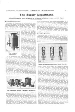
As compact an arrangement as we have seen for some time, is a new design of carburetter, of which an example has been submitted to us by Messrs. Clarkson and Co., whose works are at 200, Lichfield Road, Aston. We reproduce two photographs herewith, which will be seen to illustrate both the exterior of the complete device and the various dismantled component parts. An attempt, which appears to be a successful one, has here been made to secure the maximum of simplicity by an arrangement of all the integral parts of an ordinary carburetter concentrically with one another. In this way, it will be seen that the jet, per se, has disappeared and, in its place, the wall of the float chamber is drilled in four places, at rightangles to each other, and at a height corresponding to the top of the jet in the conventional arrangement of float feed. In a carburetter for a four-cylinder four-inch engine, these holes are .05 in. in bore.
In the illustrations, the float (B) carries, concentrically with it, a small spindle valve which finds its seating in the bottom flanged member (A) of the outside casing. It will be noticed that this base piece carries a branch union for connection to the main petrol supply. The sleeve (C) forma the walls of the float chamber itself and is a good fit into the base (A). It is this sleeve which is perforated in the manner already described, and which, thus, takes the place of the usual jet column. F is the top of the float chamber and is s:rewed into the sleeve (C) for this purpose; it is provided with a protruding tube, which carries a " float-tickling " spindle. Outside this float chamber, the outer throttle casing is screwed into the base (A). It is through the annular space that is thus formed between the sleeve (E) and the float-chamber wall (C) that the supply of air. entering through the The complete carburetter.
adjustable slots in E, passes up past the small holes in C, drawing a supply of finely-divided petrol with it, on its way up into the induction pipe through the top cover (D).
Besides the simplicity and the compact arrangement of this piece of apparatus, its designer claims for it, in action, great elasticity of supply, considerable economy in consumption, the advantage obtainable by means of the float-regulating device and the complete absence of flooding. For a 10-12 h.p. engine, this carburetter is supplied retail at £2 complete, which is a characteristic that
alone should appeal to many would-be purchasers. It is interesting to note that this form of construction enables the makers to turn out a standard motor-bicycle carburetter which only weighs 14 oz. We are informed that a number of these appliances has already been supplied, and, amongst other manufacturers who appear to be pleased with its capabilities, is the Humber Company. It is claimed that a 10-12 h.p. Humber will run 34 miles on a gallon of spirit when provided with one of these navel forms of atomizers.
Petrol Tax Recovery.
At such a time as this, when fuel for the internalcombustion engines of motor-vehicles is being made a source of revenue by the Chancellor of the Exchequer, it behoves users to neglect no possible means whereby their consumption of spirit may be reduced to the greatest possible extent. As a means to this end, a little device which is called the de Beers jet, appears to present considerable attractions. The construction of this contrivance may readily be ascertained by examination of the sketch which we publish. The jet itself is made hollow, and a small 'brass weight is made an easy fit within it. This has its exterior scored with suitablyarranged helical grooves. The weight may obtain a seating either at the top of the hollow part of the jet or at its base. The quantity of petrol delivered to the induction pipe then depends upon the pull exerted by the engine upon the jet and so upon the weight. When the engine is running at high speed the weight is said to rise, until it obtains a seating in the top of the jet, and thus reduces the supply of petrol which can only then he drawn through the restricted passages at the ends of the grooves under the seating and so round a sharp angle up to the jet orifice. On the other hand, when the engine is slowed down, the weight falls and performs a similar office at the bottom of the jet column. The principal object of this arrangement is to secure perfect atomization of the spirit on its way through the jet, clue to its passage along the helical grooves on the weight, which itself is movable, and its subsequent ejection from the jet orifice. In our opinion, it is probably largely due te this action that real economies are effected in consiimp tion, rather than to the delicate balance of the weight in the jet. However this may be, it is sufficient to know that great economies are effected by its use. Users and makers like the London General Omnibus Co. and Commercial Cars, Ltd., for example, have not placed large orders for these devices, without their first being convinced of their utility. We hear that reductions in consumption of over 40 per cent. are being achieved.