


Fig. 10 The Technicalities of
Page 44
Page 45
Page 46
If you've noticed an error in this article please click here to report it so we can fix it.
MODERN GEARBOX DESIGN
in his Concluding Article, Mr. Haigh Discusses Design Features of Synchromesh Units, Gear Selectors, and Gearboxes of the Pre-selector Type
PART 3 By A. W. HAIGH, A.M.I.Mech.E.
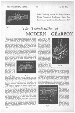
THE use of synchromesh mechanisms is, at present, confined to private cars and light commercial vehicles. No manufacturer in the heavy sphere has yet introduced a synchromesh unit as standard, the main argument against its use, on large lorries, being the wear which rapidly takes Place on the cones. This wear is caused by the high axial pressure exerted by the driver on the change-speed lever, which is necessary to overcome the inertia of the heavy gears being synchronized.
In order to reduce the inertia, or to counteract it more efficiently than with the standard synchromesh mechanisms, two courses are open to the designer. One is to reduce the weight of the gears to an absolute minimum, and the other is to increase the effective diameter of the cones.
The inertia of a revolving mass is little affected by bulk near the centre of revolution, so to reduce shaft size would be of little avail. A gear wheel can be regarded as a flywheel when inertia is being considered, and it is immediately' obvious that, because of the loca tion of the teeth on the periphery (that is, at the maximum' distance from the centre of rotation), the inertia must necessarily be fairly high. Un
fortunately, it is impossible, to remove weight from the teeth themselves, and little material can be removed from the supporting rim or gear web, if distortion in heat treatment is to be avoided and subsequent inaccurate tooth action eliminated. It must be agreed, therefore, that gears, as produced with a minimum central web and support rim, cannot be lightened, which means that inertia cannot be reduced.
The remedy of increasing the effective diameter of •the cones is likewise difficult to carry out without greatly increasing the bulk. of the synchronizing 'init. Reference to Fig. 10 shows that the dog teeth, in both gears and sliding sleeve, must be on the same diameter and that, in the existing design, the cones are located inside this diameter. To increase the diameter of the cones involves either increasing • the pitch diameter of the dog teeth, or employing internal teeth on the gears and blacker rings, and external members on the sliding sleeve, so that the cones may be outside them.
In either event, the diameter of the whole synchronizing unit must be increased. This, however, does not mean, as appears to have been concluded by many manufacturers, that synchromesh for commercial-vehicle gearboxes is impracticable. On the contrary, it should be possible to produce a synchronizing assembly without greatly modify. jug existing gearbox casings.
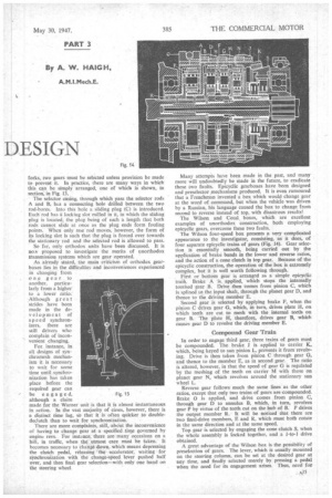
Fig. 11 At present gear selection in a . commercial-vehicle box is confined to sliding the gears themselves into mesh with one another in" crash " boxes, or selecting by means of sliding dogs in constantmesh boxes. In some "
crash" boxes, helical gears are employed, and it is necessary when sliding these gears into mesh to give them a twisting motion to accommodate the helix angle, which is done by using helical splines on the mainshafts. Many complaints against this method have been, received, however, for the thrust set up by both helical gears and helical splines tends to force the either forward or reverse speeds.
Fig. 11 shows an orthodox dog-change mechanism where each gear has additional dog teeth cut on it, which are engaged by a sleeve sliding on a hub splined to the mainshaft. The illustration shows an external type, but the internal type is equally effective.
Recently, the Gleason concern, of America, introduced a new type of face dog which it names CurVic couplings. These can be manufactured so that no thrust, tending to throw them out of action, is imparted to them during drive. Face dogs are great space savers and, as such, should be given serious consideration in gearbox design. By shortening the box, shaft lengths would be reduced and deflection decreased, th us tending towards greater quietness and reliability.
In addition to the difficulties experienced in changing gear, there is always the possibility of selecting two gears at once, as will be evident when the orthodox layout of selectorfork slots is studied (Fig. 12). If the gear-leverarm end lies across the ends of two forks, two gears must be selected unless provision be made to prevent it. In practice, there are many ways in which this can be simply arranged, one of which is shown, in section; in Fig. 13.
The selector easing, through which pass the selector rods A and B, has a connecting hole drilled between the two rod-bores. Into this hole a sliding plug (C) is introduced. Each rod has a locking slot milled in it, in which the sliding plug is located, the plug being of such a length that both rods cannot slide at once as the plug ends form fouling points. When only one rod moves, however, the form of its locking slot is such that the plug is forced over towards the stationary rod and the selected rod is allowed to pass.
So far, only orthodox units have been discussed. It is no proposed to investigate the merits of unorthodox transmission systems which are gear operated.
As already stated, the main criticism of orthodox gearboxes lies in the difficulties and inconveniences experienced in changing from one gear to another, particulady from a higher to a lower ratio. Although great strides have been made in the development of speed synchronizers, there are still drivers who complain of inconvenient changing.
For instance, in all designs of synchromesh mechanism it is necessary to wait for some time until synchronization has taken place before the required gear can be engaged, although a claim made for the Warner unit is that it is almost instantaneous in action. In the vast majority of cases, however, there is a distinct time lag, so that it is often quicker to doubledeclutch than to wait for synchronization.
There are more complaints, still,.abciut the inconvenience of having to change gear at a. specified tittle governed by engine revs. For instance, there are many occasions on a hill, in traffic, when the utmost care must be taken. It becomes necessary to change down, which means depressing the clutch pedal, releasing the accelerator, waiting for synchronization with the change-speed lever pushed half over, and then final gear selection—with only one hand on the steering wheel. Fig. 15
Many attempts have been made in the past, and many more will undoubtedly be made in the future, to eradicate these two faults. Epicyclic gearboxes have been designed and preselector mechanisms produced. It is even rumoured that a Frenchman invented a box which would change gear at the word of command, but when the vehicle -was driven by a Russian, his language caused the box to change from second to reverse instead of top, with disastrous results!
The Wilson and Cotal, boxes, which are excellent examples of unorthodox construction, both employing epicyclic gears, overcome these two faults.
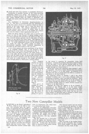
The Wilson four-speed box presents a very complicated appearance to the investigator, consisting, as it does, of four separate epicyclic trains of gears (Fig. 14)_ Gear selection is essentially smooth, being carried out by the application of brake bands in the lower and reverse ratios, and the action of a cone clutch in top gear. Because of the epicyclic construction, the operation of the box is extremely complex, but• it is well worth following through.
First or bottom gear is arranged as a simple epicyclic train. Brake A is applied, which stops the internally toothed gear B. Drive then comes from pinion C. which is splined to the input shaft, through the planet gear D, and thence to the driving member E.
Second gear is selected by applying brake F, when the pinion C drives gear G, which, in turn, drives plate H, on which teeth are cut to mesh with the internal teeth on gear B. The plate H, therefore, drives gear B, which causes gear D to revolve the driving member E.
Compound Gear Train
In order to engage third gear, three trains of gears must be compounded. The brake J is applied to carrier K. which, being keyed to sun pinion L, prevents it from revolving. Drive is then taken from pinion C through gear G, and thence to the member E, as in second gear. The ratio is altered, however, in that the speed of gear G is regulated by the meshing of the teeth on carrier 111 with those on planet gear N, which revolves around the stationary sun wheel L.
Reverse gear follows much the same lines as the other ratios, except that only two trains of gears are compounded. Brake 0 is applied, and drive comes from pinion C, through gear D to annulus B, which, in turn, revolves gear P by virtue of the teeth cut on the hub of B. P drives the output member R. It will be noticed that there are two final-drive members, E and R, which must both rotate in the same direction and at the same speed.
Top gear is selected by engaging the cone clutch S, when the whole assembly is locked together, and a I-to-1 drive obtained
A great advantage of the Wilson box is the possibility of preselection of gears. The lever, which is usually mounted on the steering column, can be set at the desired gear at any time, and finally selected merely by pressing a pedal when the need for its engagement arises Thus, need for
all hand and some foot motions is completely eliminated.
Preselection is possible because of the brake-operating mechanism, which is by spring. The mechanism is independent of manual pressure, the spring holding the box in gear being released when the pedal is depressed, and brought into action when the pedal is returned to its normal position.
The mechanism is illustrated, diagrammatically, in Fig. 15. The lever A corresponds with the operating bar in the box, and is shown in a. position where no load is applied to the brake bands, that is, when the driver has depressed the pedal. The selector mechanism on the steering column turns camshaft B. which, when in the correct position, allows strut C to be pushed into contact with strut D, which is then registered in the arm A.
When the driver releases the pedal, arm A revolves and pushes on strut D and, because of spring loading, causes it to move upwards and outwards at the joint on F (Fig. 16), This outward motion operates cam F, the point of which pushes on one end of the brake band. The opposite end of the brake band is pulled by rod F.., which is also operated by F. To avoid unbalanced stresses on the braking unit, two bands are used, the anchor points of which are .-diametrically opposite, whilst automatic adjustment is provided for the brake bands to take up wear.
A box which replaces the brake mechanism of the Wilson box by magnetic clutches, thus, to the inventor's mind, simplifying it, is the Cotal unit illustrated in Fig. 17. The drawing shows the gears in neutral, but when carrier A is slid to the right, the dog teeth on its outer circumference mesh with the teeth in gear Band provide forward drive. When the carrier is moved to the left, the dog teeth engage . with teeth on a plate secured to the casing, and drive is . taken through pinion C, which gives a reverse motion.
The magnetic clutches are shown in 1, 2,3 and 4, current for which is supplied from the car battery through brushes W, X, Y and Z. Clutch 1 is part of the primary gear D, clutches 2 and 3 are attached to the gearbox casing, w h i 1 st clutch 4 forms part of the driven shaft E.
First gear is engaged by energizing clutches 2 and 4, the drive coming from B via the sun wheel D and the planet
Fig. 16 pinions F and G
to the carrier J, armature H, meanwhile, being held stationary. Armature K is held to final-drive shaft E. hence, as the sun teeth L on K and the internal teeth on 4 are relatively 'stationary, the train is locked and the drive is straight through to 4 from carrier J.
Second gear comes into operation when clutches 2 and 3 are energized. The drive is taken directly from the primary gear D to carrier J, as in first speed. As armature H is stationary the drive is passed from the teeth L to pinion N, and thence to the final shaft E.
By supplying current to clutches 1 and 4 the whole assembly is locked, and a 1-to-1 drive, obtained, whilst the energizing of clutches 1 and 3 provides an overdrive. Drive is taken from D to the internal gear 0 on the armature H and thence through the pinion G to the carrier J. From it is passed through pinion N, which revolves around sun wheel L, to the final shaft E.
Although the Cotal box appears to be as complex in operation as the Wilson unit, it is far more simple mechanically. The complexity, in both instances, arises merely from the number of gears in operation at one time, due to the compounding of the trains, but the use of a large number of 'operating units is claimed to relieve tooth loading and improve life and reliability.