


Patents Completed.
Page 24
If you've noticed an error in this article please click here to report it so we can fix it.
A Novel Motorbus.
L. Wilton-Cox, A. Gough and E. W. Lewis.—No. 12,396, dated 23rd May, 1911. Cognate application No. 16,208 of 1911.—In this specification there is described and illustrated a motor vehicle. as for example a bus, which is adapted for service on a route where it is not possible to turn the vehicle at the end of the journey. The bus is double-ended and steering gear is provided at each end to control the adjacent pair of wheels. When running in either direction the rear pair of wheels is locked as regards steering. Duplicate control for the motor and transmission gear is also provided.
A Lynton Improvement.
R. T. Smith, No. 1321, dated 17th January, 1912.—In Lynton wheels the tires are held in position by side plates splayed out at the rim, and which grip the tire by means of a central nut on the axle. According to the present invention this side movement of the plates is made to stretch or expand the tire, or in the case of metal tires to stretch or expand segments of rubber or fibre so that the circumferential grip on the rim will be increased. The inner circumference of the tire is made wedge-shaped, and the plates are splayed out to engage this portion with a wedging action. As the plates are screwed home, the tire is forced outwards and efficiently gripped.
The invention may be applied to any form of tire by suitably forming it at its inner circumference.
An Improved Valve Spring.
E. J. J. Salmson, H. Canton and P. G. Unne, No. 9454, dated 18th April, 1911.—This invention relates to valvesprings for internal-combustion engines, especially where reliability in action is of vital importance. The springs are each constructed of a suitable length of wire helically wound into two coils, and having two double projecting arms or
bearing portions, one uf which engages the collar on the valve-stem, while the other engages a fixed abutment on the engine. By this construction the resilient portion of the spring is not subjected to heat from the cylinder, and therefore does not deteriorate.
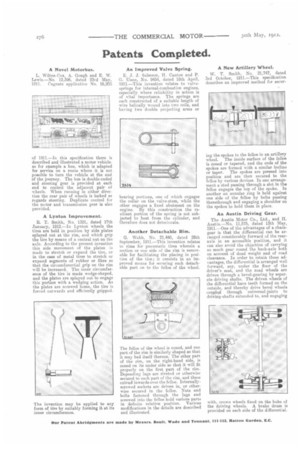
Another Detachable Rim.
G. Webb, No. 21,440, dated 28th September, 1911.—This invention relates to rims for pneumatic tires wherein a section or one side of the rim is removable for facilitating the placing in position of the tire; it consists in an improved means for securing such detachable part on to the felloe of the wheel.
The felloe of the wheel is coned, and one part of the rim is similarly shaped so that it may bed itself thereon. The other part of the rim, on the right-hand side, is coned on its under side so that it will fit properly on the first part of the rim. Depending lugs are riveted or otherwise secured to each part of the rim, and these extend inwards over the felloe. Internallyscrewed sockets are driven in, or otherwise secured in the felloe. Nuts and bolts fastened through the lugs and screwed into the felloe hold various parts in definite relative position. Various modifications in the details are described and illustrated. A New Artillery Wheel.
W. T. Smith, No. 21,747, dated 3rd October, 1911.—This specification describes an improved method for secur
ing the spokes to the felloe in an artillery wheel. The inside surface of the felloe is coned or tapered, and the ends of the spokes are formed with a similar incline or taper. The spokes are pressed into position and are then secured to the felloe by various devices. In one arrangement a stud passing through a slot in the felloe engages the top of the spoke. In another an annular ring is held against one side of the felloe by bolts passing therethrough and engaging a shoulder on the spokes to hold them in place.
An Austin Driving Gear.
The Austin Motor Co., Ltd., and H. Austin.—No. 11,575, dated 13th May, 1911.—One of the advantages of a chaingear is that the differential can be arranged considerably forward of the rearaxle in an accessible position, and it can also avoid the objection of carrying so much gear round the back-axle bath on account of dead weight and of road clearance. In order to retain these advantages, the differential is arranged well forward, say, under the floor of the driver's seat, and the road wheels are driven through a bevel-gearing by separate driving shafts. The driven wheels of the differential have teeth formed on the outside, and thereby drive bevel wheels couple,d through universal-joints to driving-shafts extended to, and engaging with, crown wheels fixed on the hubs of the driving wheels. A brake drum is provided on each side of the differential.