


Patents Completed.
Page 26
If you've noticed an error in this article please click here to report it so we can fix it.
STARTING HANDL E.—Le Clec'h and Another.—No. 18,929, dated 24th
August, 1906.—The arm or crank (k) of the handle is free on a plug (a) which is rigidly secured to the driving shaft, and the handle (n) is free to rotate in one direction on its supporting pin, but carries within it a ratchet mechanism -that is in connection with an arm (g) pivoted to the crank 0). Pivoted at f -to the crank (h) is a detent arm (b) whose nose (?) enters a recess (d) in the plug .(a). This arm is controlled by a spring (a) so that, normally, it lies beneath the arm (g), and iv engaged by a pin (j) -thereon. When starting the motor, driving is effected by rotating the crank (h) clock-wise (as shown in Figures 2 and -3), in which case the detent (e) drives the motor-shaft by means of its engage• ment with the recess (d) in the plug (a). If, however, back-firing occurs, the crank (h) will first turn slightly in the counter-clockwise direction so that the handle (n) will also be momentarily rotated in the reverse sense. This momentary rotation causes the pawl-mechanism within the handle to engage the arm (g) and lift the same sufficiently to release the detent member (b), whereupon the counter-rotation of the plug (a) causes the nose (c) of the detent member to be lifted out of the recess (d), so that the handle is released from its engagement with the shaft (as shown in Figure 3).
DIFFERENTIAL AXLE4.—Latzel.--No. 28,106, dated 5th July, 1906.—The road wheel axle (C) and its protective sleeve (A) are both undivided. The road wheel (D) is made fast to one end of the axle (C) and a sleeve or cap (E) is made fast to the other end of the axle. The ether road wheel (H) is mounted free on this cap and carries a toothed wheel (G), together with a toothed wheel (F), fast on the cap (E), and both lie within a box (L), which carries on its periphery a sprocket wheel (M). In the box (L) differential pinions (J, K) are mounted which gear with the wheels (F, G) respectively, so that power is transmitted from the wheel (M) to the road wheel (H) through the wheel (C), and to the road
wheel (D) through the wheel (F), the cap (E), and the shaft (C).
LOCKNUT.— Themke.— No. 15,394, dated 6th July, 1906.—The locking device comprises a washer (3) having gripping devices (5) on its under side, and recesses (4) on the upper face of the same. A collar (6), shaped to engage the nut, but having tongues (7), is placed between the washer and the nut. When the nut is screwed home, the tongues (7) are bent
down so that they engage the recesses (1) • in the washer, and locking is thereby effected.
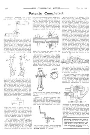
VEHICLE BODIES.—Dodson.—No. 14,510, dated 25th June, 1906.—In order that the body (d) may be readily placed in position on the chassis, blocks (a) are secured beneath the body and adapted to abut against the sides of the frame mem hers (b) of the chassis. Bolts (c) having hooked ends (c1) may be employed for securing the bOdy tn rosition.
ROAD MACHINE. — Behmer.
26,271, dated 3rd February, 1906,—For manipulating asphalt and other road material, a better result is obtained by forcing the material together by means of pressure applied vertically, as by a hammer, than is possible by rolling, as, when the material is rolled, it is also moved forward. For treating material in this way, an engine is provided with three separate series of hammers (6), all of which are separately reciprocated by pivoted arms (9) connected with a crankshaft (13). The connecting links (10) are adjustable so that the degree of lift given to each hammer can be varied; the hammers of each series are mounted upon a platform or bracket (11). This platform can be moved transversely for the purpose of bringing the hammers into a different operative position, and it can also be swung about on a pivot (19) whereby the whole series can be raised or lowered as required. The two end series of hammers preferably extend right across the main frame (4), but those placed, approximately, midway of the length of the frame are disposed at the
sides only for the purpose of working that part of the road which lies nearest the gutter. The motive power employed for driving the engine may also be used to drive the hammers.
MIXING DEVICE.—Burt.--No. 13,652, dated 14th June, 1906.—In addition to the usual inlet valve (B) an auxiliary valve (C) is employed, which controls the admission of air or inert gases through a conduit (F). The valve (C) is timed to close before the valve (B) so that, at the
beginning of the .section.__stroke, a largc proportion of air or inert gases may be drawn into the cylinder past the vale( (C) ; but, when this valve closes, the mix tore from the chamber (G), only, is drawr into the cylinder. The conduit (F) controlled by an adjustable valve (E) sc that the amount of air or inert gase allowed to pass the valve (C) may be con trolled.