


Progress in Twin-axle Driving Arrangements,
Page 36
If you've noticed an error in this article please click here to report it so we can fix it.
Resume of Recently Published Patent Specifications
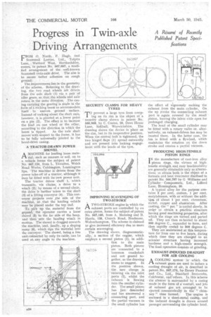
FROM 0, North, P. Hugh, and Scamrnell Lorries, Ltd., -Tolpits 'Lane, Watford' West, Hertfordshire, comes, in patent No. 567,097, a modified arrangement of the well-known Scammell twin-axle drive. The aim is to secure better adhesion on rough
ground: '
Theimprovement lies in the geometry of the scheme. Referring to the drawing, the two road wheels afe driven from the axle shaft (1) via a pair of idler gears, so that the wheels and axle rotate in the sarne direction. ,The casa ing carrying the gearing is made in the form of a rocking beam to accommodate itself to uneven ground surface. Instead of rockingabout the shaft axis, however, it is _pivoted at a lower point on a pin (2)., The effect is to increase the load on one wheel or the other, according to the direction in which the beam. is tipped. As the axle shaft moves with 'respect to the frame, it has to be fully universally jointed to the bevel-drive casing.
A TRACTOR-DRAWN POWER SHOVEL A MACHINE for loading loose material, such as manure or soil, on to a vehicle forms the .subject of patent No. 567,124, from L. Thwaites, Welch Road Works, Cubbington, Leamington Spa. -The 71:tichine is driven from the power take-off Of a tractor, although it may be fitted with its own power init. The 'tractor drives shaft 1, which transmits, via chains, a drive to a winch (2); by means of a second chain. thb driVe is further taken to the shaft (3) of a lifting conveyor (4). This conveyor projects over _the side of the machine, so' that the loading vehicle may be placed under the top end.
To pick up the material from the ground, the operator carries a loose shovel (5) to the far side of the heap, and then "sets the hauling winch in motion. The shovel is dragged towards the machine, and, finally, up a sloping ramp (6), which tips the material into the conveyor. The shovel, being a free unit connected by only its cable, can Le used at any angle to the machine.
SECURITY CLAMPS FOR HEAVY TYRES • TO prevent a large tyre from creep ing on its rim is the object of a seeurity clamp shown in patent No. 566,968, by C. Coates, 26, Dove House Lane, Solihull,. Warwickshire. The drawing shows the device in place on the rim, but in its inoperative position. When the central bolt is tightened, the two hinged flaps (1) spread outwardly and are pressed into locking engageinent with the beads of the tyre.
IMPROVING SCAVENGING OF TWO-STROKE"
ATWO-STROKE engine in which the exhaust ports are controlled by an extra piston, forms the subject of patent No. 567,160, from A. Manning and B. Harris, 135, Church Road, Bradrnore, Wolverhampton. The scheme is claimed to give increased efficiency due to more certain scavenging.
The drawing shows, diagrammatically; a section of the engine, which employs a second piston (1), in addition to the main piston. Both pistons are connected to a 'common crankshaft and not geared together, as the drawing seems to suggest. In the position shown, the new charge is. entering via the inlet ports (2), whilst the exhaust is flowing into the smaller cylinder. TheL small 'piston has just' descended and has uncovered a connecting port, and the partial vacuum in the small cylinder has
•
567124' the effect of vigorously sucking the exhaust from the main cylinder, On the up stroke the connecting exhaust port is lagain covered by the mall piston, leaving the inlets wide open for prolonged charging.
The head of the small cylinder may he fitted with a rotary valve or, alter'natively, an exhaust-driven fan may be located there. In the latter, case, the fan is fitted with a flywheel, which maintains the rotation on the down stroke and creates a partial vacuum_
PRODUCING HIGH-TENSILE PISTON RINGS
I N the manufacture of cast-iron alloy piston rings, the virtues of hightensile strength and easy Inachinahility are generally obtainable only as alternatives; to obtain both is the object of a formula and heat treatment disclbsed in patent No 566,797 by G Williams and Cylinder Components, Ltd., Lifford Lane, Birmingham, 30.
A typical alloy for the purpose contains 3 per cent. carbon, 1 per cent. molybdenum, with or without the addiLim of about I per cent. chromium-, nickel, copper and aluminium. After casting, the " pot" is cooled slowly, in order to obtain a pearlitic structure having good machining properties, after which the rings are turned and parted off. They are then re-heated to about 900 degrees C., expanded to form, and then rapidly cooled to g00 degrees C.
They are maintained at this temperature for'frorn one to five hours, during which time they are changed -to an acicular structure having increased hardness and a high-tensile strength. The final operation consists of grinding.
EXHAUST-INDUCED DRAUGHT FOR AIR COOLING
A COOLING system in which the ri exhaust gases are used to induce a cooling draught of air, is described in patent No. 567,173, by-Davey Paxman and Co., Ltd., Standard Ironworks, Colchester, ancrothers. In this scheme the silencer is surrounded by a casing made in the form of a venterri, and jets of exhaust gas are arrangedto be ejected concentrically in the'"' chim
ney !' thus formed.The engine is enclosed in a sheet-metal casing, and the induced draught is dmwn around passages surrounding the cylinder head.