


A NOVEL FORM OF GEAR TOOTH.
Page 34
If you've noticed an error in this article please click here to report it so we can fix it.
A Resume of Recently Published Patent Specifications.
SAM SUNDERLAND, of Keighley, and of gear-planer fame, and A. M. klidgley, in their specification No. 247,685, point out that it is possible to maintain the necessary strength of a gear tooth and, at the same time, to reduce the angle of pressure on the driving side of the tooth. It is clear that, in the gearing used in the change-speed mechanism of a motorcar, the teeth of such gears are called aeon to withstand a very great load on the driving side, whilst on the reverse side no load greater than that necessary to turn the engine round can ever be exerted. It is also well recognized that the nearer the angle of the tooth approximates to a radial line, the less the load on the bearings due to the shafts baying a tendency to ride apart from each other, owing to the angle of pressure employed. It is also well known that teeth can be formed so that gears would keep in mesh, even if one shaft were mounted on slidable bearings, but such teeth
have in the past • been found weak owing to the' fact that they were not sufficiently strong at the flank.
..M-R-11-1The inventors ' have overcome this difficulty by making the rack, which is employed in the well-known Sunderland planing process, so that the angle is unequal, as shown in the upper view. The tooth form produced by this rack is shown in the lower view, it forms a strong buttress to resist pressure on the non-driving side, whilst it allows a more suitable form to be employed on the driving side.
A Gear-grinding Machine.
THE Churchill Machine Tool Co., Ltd., the well-known makers of grinding machines, describe in specification
No. 247,893 what is claimed to be an improvement in Jnaehines for grinding the teeth of gears with the fiat face of an abrasive wheel. The machine bears a close resemblance to the well-known Lees-Bradner machine, in which the rolling of the face of the grinding wheel, controlled by accurate mechanism, develops the desired tooth form. In the specification reference is made to the patents of Noyes (No. 107,608) and to Hoeft (No. 159,503).
The specification and drawings are not very clear, but the plan appears to be one in which the gear to be ground is fixed to a mandrel to which is also, fixed a gearwheel of double its diameter.
The larger wheel meshes with a rack, which imparts to the gears a rolling motion as the slide on which they are mounted rises and falls by means of a crank. Fixed to the name shaft which carries the gears is a template, which has a special form of perit phery.
The periphery of this template bears against a roller which is mounted on a pin attached to some stationary part of the machine.
As in the Lees-Bradner machine, only one side of each tooth is ground at a time, and when that tooth is com pleted the gear is brought clear of the grinding wheel so that the index may be moved to the next tooth ; and it would seem that the gear to be ground would require reversing on its mandrel to enable the opposite side of the teeth to be ground. No mention is made of any means of providing for the wear which must take place on the abrasive wheel, or of any means of truing the working face.
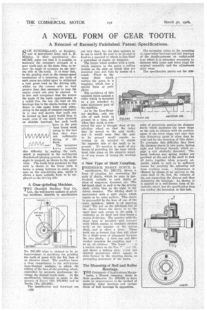
A New Type of Shaft Coupling.
FREDERICK HARRY ROYCE, in
specification No. 242,171, shows a form of coupling for connecting the ends of shafts, which he says is particularly suitable to such shafts as those of magnetos, dynamos, etc. The left-hand shaft is said to be the driving shaft, whilst that on the right is the driven member. The driving shaft is surrounded with a split sleeve which tapers on its outer surface. This sleeve Is surrounded by the boss of one of the main members, which is of tapering form:" The nut on the left-hand end of the sleeve draws the sleeve in to the taper boss and, owing to the split, it contracts on its shaft and thus forms a means of driving. The member with the taper boss is provided with internal teeth whieb engage in similarly pitched teeth on the member on the driven shaft, and so effect a drive. These teeth are so formed that they will allow for a slight error of alignment between the two shafts. A dust cap and fibre washer complete the coupling, and .t.
as an oil retainer. The lower is a section taken on the line :Ir.] (2),
and shows a locking plate te'iich has internal projections whiell engage in slots formed in the tapering sleeve, so preventing movement of the latter.
The Mounting of Ball and Roller Bearings.
TEE Compagnie d'Applications Mecan
iques, a French company, claim in their specification No. 236,541 to have made an improvement in the method of mountine•' roller bearings and certain kinds of ball bearings in opposition.
The invention refers to the mounting of taper-roller bearings and ball bearings of the double-purpose or radial-axial type where it is necessary accurately to distance both inner and outer rings for original assembly and for adjustment after wear.
The specification points out the diffi
culty of accurately spacing the distance sleeve which separates the inner rings on the axle in relation with the position apart of the outer rings, and says that this distancing apart is often done by trial and by the inserting of thin shims. To overcome this difficulty they form the distance sleeve in two parts, having right and left-hand threads, which engage a nut similarly threaded. The aasual lock-nut and spring washer are provided at the end of the shaft to lock all parts together when properly adjusted, which is said to be sufficient means for securing the adjusting nut
from working loose. Adjustment is effected by means of an opening in the outer shell of the hub, the rotation of the nut separating the sleeves and thus distancing the bearings. As shown, it is applied to a well-known form of detachable wheel, but the specification does not confine the invention to this hub.