 1
1 2
2 3
3 4
4 5
5 6
6 7
7 8
8 9
9 10
10 11
11 12
12 13
13 14
14 15
15 16
16 17
17 18
18 19
19 20
20 21
21 22
22 23
23 24
24 25
25 26
26 27
27 28
28 29
29 30
30 31
31 32
32 33
33 34
34 35
35 36
36 37
37 38
38 39
39 40
40 41
41 42
42 43
43 44
44 45
45 46
46 47
47 48
48 49
49 50
50 51
51 52
52 53
53 54
54 55
55 56
56 57
57 58
58 59
59 60
60 61
61 62
62 63
63 64
64 65
65 66
66 67
67 68
68 69
69 70
70 71
71 72
72 73
73 74
74 75
75 76
76 77
77 78
78 79
79 80
80 81
81 82
82 83
83 84
84 85
85 86
86 87
87 88
88 89
89 90
90 91
91 92
92 93
93 94
94 95
95 96
96 97
97 98
98 99
99 100
100 101
101 102
102 103
103 104
104 105
105 106
106 107
107 108
108 109
109 110
110 111
111 112
112 113
113 114
114 115
115 116
116 117
117 118
118 119
119 120
120 121
121 122
122 123
123 124
124 125
125 126
126 127
127 128
128 129
129 130
130 131
131 132
132 133
133 134
134 135
135 136
136 137
137 138
138 139
139 140
140 141
141 142
142 143
143 144
144 145
145 146
146 147
147 148
148 • Three Variable Gears
Page 110
If you've noticed an error in this article please click here to report it so we can fix it.
A Msurn4 of Recently Published Patent Specifications
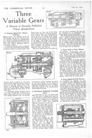
A Change Speed for Heavy Vehicles.
THE patent, No. 392,572, of W. H. Bramble and Ruston and Hornsby, Ltd., Lincoln, relates to a change-speed gear which is specially designed for very heavy work such as that in connection with road rollers, armoured cars or extra-heavy lorries.
A clutch of the disc type is arranged to operate each of the three gears shown, all pinions being in constant mesh. The primary shaft is geared to the main shaft,'-which carries the pinion (G1) at the rear end, the clutch plate (G2), which is slidablyt mounted, near the centre and the pinion which engages with that behind the bevel gear, at its front end.
A constantly driven housing having end walls (P-,and K) is driven by a sleeve and a gear (D) and is provided with axially slidable rings (0 and M). These rings eau grip any of the three clutch plates shown, to produce the gear ratio required. They are controlled by means of the two sliding muffs which can operate the levers (11) and sliding rods (8) which regulate the movements of the rings. The single clutch plates are all slidably mounted, so that only a movement of the gripping ring on one side is needed, the sliding movement being sufficient to produce the necessary clearance when not driving.
The forks which operate the muffs are
controlled by a lever working in a gate, so that the freedom of one clutch is assured before another can be engaged. Although entailing the use of many parts, this appears to be a particularly sound engineering job.
A Frictional Infinitely Variable Gear.
ALTHOUGH we have but little faith
in any kind of change-speed gear in which friction is relied upon to transmit torque, that described in the patent of F. A. Hayes, Middletown Township, New Jersey, U.S.A., and numbered 392,570, contains a novel feature. The main plan of employing a friction disc between two members each of which has a groove the contour of which is a semi-circle, the disc being able to assume various angles and so impart a variable speed to its carrier is, however, by no means new' and is described in many text books.
The novel feature in the present instance is that two sets of intermediate friction discs may be used in the same grooves, one set acting as drivers and one set acting as the driven. Both the inner members (15 and 17) are fixed to the driving shaft, whilst both the driven members (16 and 18) are attached to a bell-shaped part which forms the driven member.
The friction discs (110 and 111) impart a reduced speed to the carrier (115). This is provided with two arms, not shown, which carry friction discs, one of which is shown in broken lines, set at another angle to those shown in full lines. The angle of both discs may be altered so that a much greater variation of speed can be obtained.
A Gear with a Free Wheel.
ANOTHER change-speed gear is
shown in patent No. 392,818 by Fernand jouan, 80, rue Saint-Lazare, Paris. Dog engagement is employed for all gears, also for locking the free wheel which is provided.
The construction of the free wheel is somewhat novel, as the kills (57) are arranged to run up inclines when the two parts run in one direction, thus causing a cage to move so that the rollers (62) run up slopes of a similar kind on a member (14), which is an enlarged portion of the driven shaft. A sliding member (35) engages the second speed when moved to the left, and locks the free wheel when moved to the right. Another member (34) is for engaging either third or fourth speed.
A Free-wheel-at-will Device.
A PATENT, No. 389,642, has been
granted to Free Wheeling Patents, Delaware, U.S.A., an American corporation, for a device which provides a free wheel on the top gear and the next higher gear, but which can be converted to a hi-directional drive.
Unidirectional clutches of the coilspring type are fitted inside drums, one fast to the driving shaft and one splined to the driven shaft. A central member can be moved to the right to lock the free wheel of the nearest gear to top gear and to the left to lock top gear.
There appears to be no arrangement for picking up a stalled engine.