


Electrostatic Cleaner for Producer Gas
Page 34
If you've noticed an error in this article please click here to report it so we can fix it.
-THE principle of cleaning gas electro
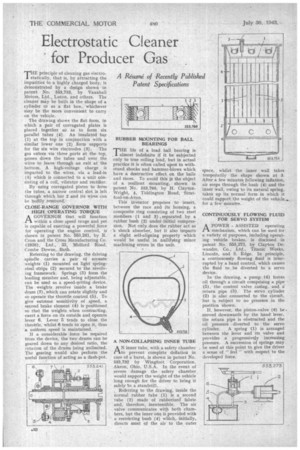
statically, that is, by attracting the impurities to a highly charged body, is demonstrated by a design shown in patent No, 553,753, by Vauxhall Motors, Ltd., Luton, and others. The cleaner may be built in the shape of a cylinder or as a flat box, whichever may be the more Convenient to carry on the vehicle.
The drawing shows the flat form, in which a pair of corrugated plates is placed together s6•as to form six parallel tubes (4). An insulated bar • (I) at the top in conjunction with a similar lower one (2) item supports for the six wire electrodes (3). The gas enters via three ports at the top, passes down the tubes and over the wires to leave through an exit at the bottom. A high-voltage charge is imparted to the wires, via a lead-in (5) which is connected to a unit consisting of a coil, vibrator and rectifier.
By using corrugated plates to form the tubes, a narrow central slot is left through which bar 2 and its wires can be bodily removed.
CLOSE-RANGE GOVERNOR WITH HIGH. OPERATING TORQUE
A GOVERNOR that will function • PI within a close speed range and yet is capable of exerting a powerful .force for operating the engine control, is shown in patent No. 553,241, by R. Cross and the Cross Manufacturing Co. (1938), Ltd., 33, Midford Road, Combe Downe, Bath.
Referring to the drawing, the driving spindle . carries a pair of arcuate weights (1) mounted on light springsteel strips (2) secured to the revolving framework. Springs (3) form the loading member and, being adjustable, can be used as a speed-s.etting device. The weights revolve inside a brake drum (7), which can rotate slightly and so operate the throttle control (5). To give extreme sensitivity of speed, a second brake element (4) is positioned so that the weights when contracting, exert a force on its outside and operate lever 6. Lever 5 tends to close the throttle, whilst 6 tends to open it, thus a uniform speed is maintained.
If a considerable force be required from the device, the two drums can be geared down to any desired ratio, the rotation of the drums being unlimited. The gearing would also perform the useful function of acting as a dash-pot. RUBBER MOUNTING FOR BALL BEARINGS THE life of a load ball bearing is , almost indefinite if it be subjected Only to true rolling load, but in actual practice it is often called upon to withstand shocks and hammer-blows which have a destructive effect on the balls and races. To avoid this is the object of a resilient mounting, shown in patent No. 553,760, by H. ClaytonWright, 4, Tiddington Road, Stratford-on-Avon.
This inventor proposes to insert, between the race and its housing, a composite ring consisting of two steel members (1 and 3) .separated by a rubber bush (2) under initial compression. Not only does the rubber act as 'a shock absorber, but it also imparts a slight self-aligning property which would be useful in nullifying minor machining errors in the unit.
A NON-COLLAPSING INNER TUBE
AN inner tube, with a safety chamber to prevent complete deflation in case of a burst, is shown in patent No. 553,732 by Wingfoot Corporation, Akron, Ohio, U.S.A. In the event of severe damage the safety chamber would support the weight of the vehicle long enough for the driver to bring it safely 'to a standstill.
, Referring to the drawing, inside the normal rubber tube (1) is a second tube (2) made of rubberized' fabric and, therefore, inextengible. The air valve communicates with both chambers, but the inner one is provided with a restricting bush (4) which, initially, directs most of the air to the outer space, whilst the •inner wall takes temporarily the shape shown. at 3. After a few minutes following inflation, air seeps through the bush (4) and the inner wall, owing to its natural spring, takes up its normal form in which it could support the weight of the vehicle... for a few minutes.
CONTINUOUSLY FLOWING FLUID FOR SERVO SYSTEM
A POWER ASSISTED operating .1—t mechanism, which can be used for' a variety of purposes, including operating vehicle brakes, is disclosed in patent No. 553,273, by Clayton Dewandre, Co.; Ltd., Titanic Works, Lincoln, and S. Edge. In principle, a continuously flowing fluid is interrupted by a hand control, which causes the fluid to be diverted to a servo device.
In the drawing, a pump (4) forces oil through a circuit comprising a pipe (5), the control valve casing, and a return pipe (3). The servo cylinder (2) is also connected to the circuit, but is subject to no pressure in the position shown.
If, however, the piston-valve (6) be. moved downwards by the hand lever, the return pipe is obstructed and the oil pressure . diverted to the servo cylinder. A spring (1) is arranged between the lever and its valve and provides a progressively increasing pressure. A succession of springs may he used at this point to give the driver a sense of " feel " with respect to the developed force.