


Lubrication Systems for Commercial Vehicles.
Page 2
Page 3
If you've noticed an error in this article please click here to report it so we can fix it.
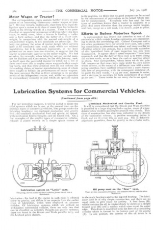
(Continued from page 489.) For our immediate purpose, it will be useful to divide the chief systems which are in use, at the present time, on the principal types of commercial vehicles, into groups under the following headings : (a) combined mechanical and gravity feed ; (b) combined mechanical feed and splash ; (c) splash, with mechanical feed to troughs ; and (d) forced feed. On a few examples of the smaller types of commercial vehicles, reliance is placed entirely on a simple splash system of lubrication ; the feed to the engine in such cases is effected solely by gravity, and differs in no respects from the earlier types of lubrication, which were employed On pleasure vehicles. Of lubrication systems, which are utilised on well-known commercial vehicles, there are only two that can be classified as definitely thought-out gravity systems; these are found in the Broom and Wade paraffin lorry, and The Leyland petrol chassis. Combined Mechanical and Gravity Feed.
it will be remembered that the Broom and Wade machine is propelled by a large single-cylinder engine, many of whose details follow modern gas-engine practice very closely. This class of construction has also been embodied in the details of the lubrication scheme. A positive measuring device is fitted, and we illustrate this on page 505. Oil, in definitely adjustable quantities, flows by gravity to the cylinder walls, to the main bearings and to the big-end bearing. The lubricator itself is of very simple construction, and there are no small parts to give cause for anxiety. A feed drum (B), which contains the oil, is rotated slowly by means of a simple hinged pawl (H) and a ratchet which runs round its upper edge. This drum is machined to fit the bore of a containing cylinder which is formed in the bottom part of the casing (A). In one position, the interior of this oil drum is in
communication (G1) with four small horizontal chambers in the outer casing ; the capacity of these small chambers (G) is variable by means of the thumb-screws. (D), which can be adjusted from outside. The continuance of the rotary motion of the central oil drum cuts off this communication, and s-ubsequently connects the horizontal chambers, which are now full of oil, with vertical passages which allow the lubricant to pass to the various parts of the engine by gravity. The oil pipes lead to the cylinder walls, to the main bearings of the crankshaft, and to a "banjo " which is fixed on to one of the crank webs. Oil drips into this lastmentioned fitting, and the rotation of the crank forces the oil centrifugally up into the big-end bearing. The lubrication pipes are kept as short as possible, and are made of cold-drawn steel tube, with copper ferrules brazed on to the ends. The makers claim, on behalf of the simple gravity system which they have adopted, that the lubricator requires positively no other attention than filling every two days. in feeding the bearings, they say, with a tube full of oil at intervals, the oil has less chance of dispersing itself through the " interstices "-of the bearing, without distributing itself properly over the surface, than it has with the constantdrip system. A very heavy class of oil can be used on the Broom and Wade installation, owing to the large bore of the pipes through which the lubricant has to pass. As a horizontal paraffin engine is employed on this vehicle, the makers concluded that it would be inadmissible to employ the splash system of lubrication, owing to the tendency there would have been for the oil to become diluted with unconsurned paraffin. The Leyland Gravity System.
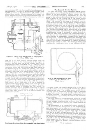
The other well-known type of commercial motor vehicle, upon which a form of the gravity system is successfully employed, is the petrol-propelled Leyland chassis. On this model, circulation is ensured by the provision of a small oil pump of the ordinary, intermeshed, gear-wheel type, and this is located on the exhaust side of the engine, and is operated by an arrangement of Worm gearing on the camshaft. The function of this pump is to draw oil from the sump in the crank case, and to force it up into the main reservoir which is carried on the dashboard. Copper pipes of unusually large bore lead to the three main crankshaft bearings, and the oil continuously finds its way down there by gravity. The main journals, the webs, and the crank pins are drilled to enable the oil which is fed to the main hearings to reach the big-end brasses. The end wall of the crank-chamber casing is arranged to project beyond the end of the outer crank bearings, and is designed in such a way that any oil, which may work through to the ends of these journals, is automatically returned to the bottom of the crank case. • A gauge is provided on the dashboard, and this indicates the amount of oil that is contained in the reservoir; in this way, any cessation of work on the part of the pump can always be noted. The makers of the Leyland machines lay considerable stress on the efficiency of their
lubrication, which they claim to secure owing to the spraying effect of the oil as it is flung off from the big ends of the connecting rods. The Leyland system avoids the uncertainty which is inseparable from an attempt to maintain a fixed oil level in the crank chamber when the splash system is employed. The large pipes in the Leyland system should eliminate any possibility of failure of the circulation due to choking. The same method of oil distribution is utilised by several other well-known makers, with the important exception that the oil is again forced from the reservoir down into the bearings, and thence out through the crank webs to the big ends.
The embodiment of a gravity-feed • system undoubtedly results in considerable simplification of the mechanical details of an engine, but, in order to ensure absolute certainty of operation, it would seem advisable to employ some form Of mechanical-feed appliancetogether with pipes of ample size, and of as short a length as possible. To enable our readers the more readily to realise the problem which the manufacturer has before him in his choice of a reliable and yet comparatively inexpensive system of lubrication, we have included, on this and the previous page, illustrations which show respectively the expensive machining and the additional extra fittings, for which a carefully-designed forcedfeed system calls.