


Automatic Trailer Steering
Page 60
If you've noticed an error in this article please click here to report it so we can fix it.
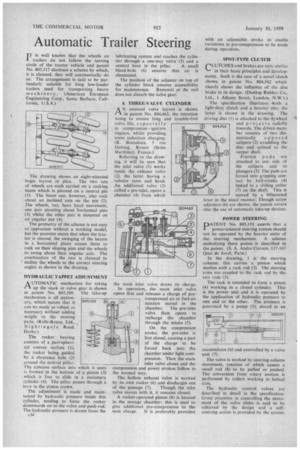
I T is well known that the wheels on trailers do not follow the turning circle of the tractor vehicle and patent No. 805,317 discloses a scheme by which, it is claimed, they will automatically do so: The arrangement is said to be particularly suitable for long low-loader trailers used for transporting heavy m achiner y. (American European Engineering Corp., Santa Barbara. California, U.S.A.) The drawing shows an eight-wheeled bogie layout in plan. The two sets of wheels are each carried on a rocking beam which is pivoted on a central pin (I). The beam can, however, also rock about an inclined axis on the pin (2). The wheels, too, have local movement, one pair pivoting about horizontal pins (3) whilst the other pair is mounted on an angular pin (4), The geometry of the scheme is not easy to' appreciate without a working model, but the patentee states that when the tractor is steered, the swinging of the beams in a horizontal plane causes them to rock on their sloping pins and the wheels to swing about their angular axis. The combination of the two is claimed to incline the wheels to the correct steering angles as shown in the drawing.
HYDRAULIC TAPPET ADJUSTMENT
AUTOMATIC mechanism for taking up the slack in valve gear is shown in patent No. 805,109. The take-up mechanism is all stationary, which means that it can be made as robust as necessary without adding weight to the moving parts. (Rolls-Royce, Ltd.„ Nightingale Road, Derby.) The rocker bearing consists of a part-spherical convex surface (1), the rocker being guided by a clearance hole (2) around the central pillar. The concave surface into which it seats is formed in the bottom of a piston (3) which is free to slide in a stationary cylinder (4). The pillar passes through a bore in the piston crown.
The adjustment is made and maintained by hydraulic pressure inside this cylinder, tending to force the rocker downwards on to the valve and push-rod. The hydraulic pressure is drawn from the A34 lubricating system and reaches the cylinder through a one-way valve (5) and a central bore in the pillar. A small bleed-hole (6) ensures that air is eliminated.
The position of the adjuster on top of the cylinder block ensures accessibility for maintenance. Removal of the unit does not disturb the valve gear.
A THREE-VALVE CYLINDER A N unusual valve layout is shown in patent No. 804,465, the intention being to ensure long and trouble-free valve life, especially in compression ignition engines, whilst providing some induction charging. (R. Bouteleux. 5 rue Dulong, Rouen (Seine Maritime). France.) Referring to the drawing, it will be seen that the inlet valve (1) works inside the exhaust valve (2), the latter having a tubular stem and head. An additional valve (3) called a pre-inlet, opens a chamber (4) from which
the main inlet valve draws its charge.
In operation, the main inlet valve opens first and releases a charge of precompressed air or fuel-air mixture stored in the chamber. The pre-inlet valve then opens to recharge the chamber through the intake (5).
On the compression stroke, the pre-inlet is first closed, causing a part of the charge to be forced back into the chamber under light compression. Then the main inlet valve closes and the compression and power strokes follow in the normal way.
The hollow exhaust valve is worked by its own rocker (6) and discharges out of the passage (7). 'Though the inlet valve moves with it. it remains closed.
A rocker-operated piston (8) is located in the storage chamber; this is used to give additional pre-compression to the next charge. It is preferably provided with an adjustable stroke to enable variations in pre-compression to be made during operation.
SPOT-TYPE CLUTCH CLUTCHES and brakes are very similar in their basic principles and developments. Such is the case of a novel clutch shown in patent No. 804,562 which clearly shows the influence of the disc brake in its design. (Dunlop Rubber Co., Ltd., 1 Albany Street, London, N.W.1.) The specification illustrates -both a light-duty clutch and a heavier one; the latter is shown in the drawing. The driving disc (I) is attached to the flywheel and pro jects radially inwards. The driven member consists of two diametrically opposed calipers (2) straddling the disc and splined to the output shaft.
Friction pads are attached to one side of the calipers and to plungers (3). The pads are forced into gripping contact by bell-cranks (4) linked to a sliding collar (5) on the shaft. This is moved by a bifurcated lever in the usual manner. Though screw adjusters (6) are shown, the patent covers also the use of automatic take-up devices.
POWER STEERING
PATENT No. 805,193 asserts that a power-assisted steering system should not be operated by the heavier units of the steering mechanism. A scheme embodying these points is described in the patent. (S. A. Andre Citroen, 117-167 Quai de Javel, Paris.)
In the drawing, 1 is the steering column; this carries a pinion which meshes with a rack rod (2). The steering arms are coupled to the rack rod by the two rods (3).
The rack is extended to form a piston (4) working in a closed cylinder. This is the power unit and it is operated by the application of hydraulic pressure to one end or the other. The pressure is generated by a pump (5), stored in an
accumulator (6) and controlled by a valve unit (7).
The valve is worked by steering column movement, rotation of which causes a small rod (8) to be pulled or pushed. The conversion from rotary motion is performed by rollers working in helical slots.
The hydraulic control valves are described in detail in the specification. Great precision in controlling the niovement of the valve slides is said to be achieved by the design and a selfcentring action is provided by the system.