


AN INGENIOUS TRANSMISSION GEAR.
Page 34
If you've noticed an error in this article please click here to report it so we can fix it.
A Résumé of Recently Published Patents.
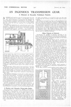
ASIMPLE and ingenious form of change-speed gear has been patented by H. Mebbs, of the Pytchley Autocar Co., Ltd., and is described in specification No. 190,001. It can be Adapted, in various coostructions' to which reference is made in the specification, for two three, or four speeds. The one which we will now describe is a two-speed and reverse gear.
The principal 'components are a twin flywheel and a twin. disc clutch. By the use of these the two-speed gear is made possible, in conjunction with the use of the engine camshaft as one of the shafts of the "gearbox.' The two flywheels axe mounted close together, one, on the engine shaft, very much as usual; the other is on a tubular shaft, which is mounted outside, and concentric with, the engine shaft. The movable clutch member envelops the two flywheels, and is so arranged that, moved to the limit of its motion in one direction, a friction f see comes in contact with one of the flywheels, and, when it is similarly moved in the other direction, another friction face comes into contact with the other flywheel. Iri this way the drive ie transmitted to the clutch member from one or ethos of the flywheels, according to the position of the clutch7It is understood, of course, that a neutral position is obtained when the movable part of the clutch is in midposition.
For the top gear, which is direct, the transmission is through the flywheel, which is mounted on the engine shaft. For the second speed the other flywheel, mounted on the hollow shr. on the engine shaft, is used, the actual transmission of the power being through the carnshaft, and then ..by means of a pair of gears which connect the camshaft to the aforesaid hollow shaft.
The method of obtaining a reverse gear is rather ingenious. On the end of the camshaft is mounted a. cone-shaped member which can be slid endwise. The flange of the clutch member, which, as has been stated, envelops the two flywheels, is shaped to engage with this Member on its being moved forward to the required extent. The -reverse drive is thus from engine shaft to camshaft, then by, means of the conical member on the camshaft to the clutch member, which, when this gear is engaged, is in the mid or neutral position of its travel. It is by amplification of both these devices—the use of reducing gears between camshaft and tubular layshaft, and the employment of a conical friction reember—that the additional changes are Obtained on the three and four-speed boxes.
A Ruston and Hornsby Water-tube Boiler.
It is not stated,: in spreification No. 189,935, in which Ruston and Hornsby, Ltd., describe a form of vertical water-tube boiler, that it is designed for use in steam wagous, but it certainly appears to be a steam generator which would be admirably adapted for that purpose. The invention is concerned with the arrangement of the tubes in the boiler, which are set out so that it is not necessary, when they are to he cleaned, to separate the outer shell of the boiler from the inner. They_ are. accessible, for., that purpose, through handholes of reasonable size. Moreover, it is unnecessary to flatten
134 the aides of the firebox, or to bend the tubes near the ends,, in order that the necessary. number of tubes may be accommodated.
The tubes are arranged in groups—in the specification four tubes are shown to each gratin, and they are disposed so that they are as the four corners of a diamond. Each group has' its own particular hand-hole in the boiler shell, the shape of the group, being convenient to that: end, and to the use of a small hand-hole. Reference to one of the accompanying illus.: trations will be of interest as indicating the arrangement of the hand-holes and of the different groups of tubes, which are disposed in pairs. The number of groups varies; three pairs are shown, arranged one pair below the other, and croes, ing the boiler in different directions.
Other Patents of Interest.
• Specification No. 181,390, by Scintilla, .describes an improved method of signalling to the driver the relative conditions of the dynamo and battery of the electrical equipment, as to whether the former is charging the latter, or the latter . • tending to discharge the former. Specification-No. 184,786, by Staub and Co.,. describes an improved type of spring gaiter. The joint is at the top, and. the gaiter isheld by means of suitable distance-pieces located at the corners of the spring, and Along it length, at such a distance from the spring that the space thus left accommodates ample lubricant, Which the inventor recommends should • he oil, retained, if necessary, by some spongy material.
The coil spring unit, which is a feature of the springing system which is described in specification No. 190,504, is located between the downwardly depending arms of two bell• crank levers, the horizontal arms of which project inwardly towards one another, and have flat upper surfaces with which engage the cam-shaped undersides of a double-armea. lever, the pivot of which is over the centre of the spring, and is, •• therefore, also midway between the bell-crank levers. The • spindle of the horizontal lever is connected, in one way or another, to the vehicle axle, so that, as it rises and falls the lever is oscillated. The cam-shaped underside of this fever is designed so that for normal vibrations of the axle the spring resistance increases uniformly with the movement, ' but when that movement extends beyond the normal the resistance increases more rapidly, but without causing endue: shock to be transmitted to the, chassis. The patentees are the Monarch Door Controller Co., Ltd.
A rather clever type of box spanner, which embodies a universal joint in the handle, is described in specification No. 190,673, by J. McGhee. E. D. Perry mounts a small auxiliary steam engine on the ; side of the water jacket of an internal-combustion engine. He derives the steam for this engine from the cooling water of the i.-c. engine, the steaming capacity being increased by the adoption of specially arranged radiating fins within the jacket, designed to improve the conduction of heat from the cylinder to the Water.
'The method of braking . described in specification No. 199,502 by G. S. Crawford consists of a pair of shoes, mounted Dn brackets to swing about the wheel axles, and carrying rollers so arranged that, when the shoes are lowered, and the rollers are in contact with the . ground, the car wheels, run• meg upon these rollers, cause them to revolve in the opposite directon to that of the wheels themselves, thus tending to drive the eat' in the contrary direction, and, therefore, considerably in creasing the braking effort. •