


Patents Completed.
Page 28
If you've noticed an error in this article please click here to report it so we can fix it.
Complete specifications of the following patents will be sent to any address in the United Kingdom by the Sales Branch, Patent Office, Holborn, W.C., upon receipt of eightpence per copy.
Another Reid-Riekie Wheel.
A. T. Reid, and J. Riekie, No. 9364, dated 20th April, 1912.—This spring wheel is of the type in which helical or
other springs are arranged in compression between an inner and an outer rim,
and are free to move circumferentially. In this instance blocks of rufolier, or similar resilient material, are asseeiated
with the springs, three variations being shown in the accompanying drawing. The block of rubber may be solid as shown un the left-hand side, or hollow as shown in the centre, if increased resilience is required. On the right-hand side the helical spring is embedded in a hollow rubber block. Distance pieces are provided on the outer rim to engage the shoes in which the springs are seated, and to prevent excessive circumferential motion. The surface of the inner rim is lubricated by blocks of solid lubricant, shown on the left-hand side of the centre spring. Various alternatives are also described and illustrated in the specification.
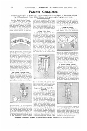
An Albion Throttle Valve.::
Albion Motor Car Co., Ltd., and T. B. Murray, No. 27,073, dated 4th December, 1911.—This specification describes a controlling valve in which the air valve and the gas valve are of the mushroom type, and are mounted concentrically on the same spindle. In the construction illustrated, an air-inlet valve is shown on the right and the combined valve on the left. The air enters through the valve on the right and passes downwards into the conduit at the bottom of the casing. It passes out upwards through the lower of the two concentric mushroom valves to the intermediate conduit through which the gas is supplied. The mixture then passes on and upwards to the upper conduit through the upper and larger of the concentric mushroom valves which therefore acts as the main throttle valve. There is also illustrated in this valve the pilot valve for light running that is described in Patent o. 15,585, of 1910.
A New Valve Gear.
A. J. Drake, No. 565, dated 8th January, 1912.—In this engine two valves are provided side by side ; one, however, is utilized as a two-stroke engine and power is obtained from it. The main piston is on the right, and the combustion chamber in its cylinder communicates also with the cylinder of the central piston which acts as a valve by controlling the port between it and the piston valve on the left. The central piston is geared to the main piston so as to run at half speed, and therefore operates as a twocycle engine when the main piston is being operated as a four-cycle engine. The piston valve on the left directs the
flow of the inlet and exhaust gases. 'Phis construction is stated to allow the use of large ports and to ensure rapid opening of the passage for the gases.
Improved Driving Chain Construction.
A. J. Rowledge and the Wolseley Motor Car Co., Ltd., No. 25,978, dated 21st November, 1911.—According to this invention the manufacture of silent chains is cheapened very considerably, and the chains are made stronger without increasing thc size, by doing away with the hardened bushes for the pins. The links are made of a fairly soft steel, it rid after the holes for the pins have been drilled. ,.fiey are endue-hardened on the interior by a brief but intense heating. This may he done by an oxy-acetylene flame, or by directing an electric arc across the surface. In the latter case it is preferable to pass the arc right through the hole and not to use the link as one of the electrodes. The preferred system is to harden the holes while the metal, from which the links are cut, is in one continuous strip, as there is then
better provision for the rapid conduction of the heat away from the treated surface. It will be seen that, without increasing the size of the link, by this means the rivet can be larger.
A New Oil Gauge.
E. H. Trelease, No. 18,790, dated 16th August, 1912.—This specification describes an indicator for the oil eireu lation on a chassis, in which the movemeat of the pointer is controlled by a piston moving in a cylinder which is open to the presence of the oil supply. A spring or weight is provided on the piston to oppose the oil pressure' and a distinctive pointer is provided to show the pressure of the oil supply.
A Double-acting Engine.
S.W. Carlton, No. 27,833, dated 11th December' 1911.—This specification describes a double-acting four-stroke-cycle internal-combustion engine in which two cylinders are arranged in tandem. Under these conditions the engine gives one impulse for every stroke. A trunk-piston member is used to carry the two working pistons which are provided with rings in the ordinary way. The two combustion spaces, adjacent to one another' between the working pistons, are separated by a
water-cooled partition which is bored to form a guide for the piston trunk. This trunk is made hollow from end to end, and is provided with internal ribs so that efficient cooling can be obtained by circulating air through it. The piston head is extended downwards into the trunk and has two rings at its lower end