


A German Electric Cab.
Page 17
Page 18
If you've noticed an error in this article please click here to report it so we can fix it.
One of the Novelties at the Recent Commercial Motor Show in Berlin.
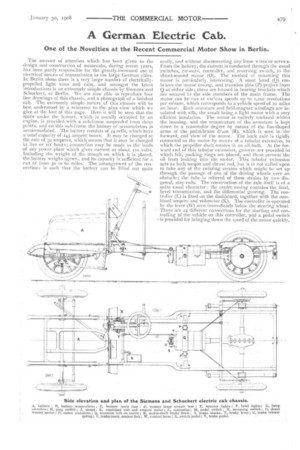
The amount of attention which has been given to the design and construction of motorcabs, during recent years, has been partly responsible for the greatly-increased use of electrical means of transmission in the large German cities. In Berlin alone there is a very large number of electricallypropelled light vans and cabs, and amongst the latest introductions is an extremely simple chassis by Siemens and Schuckert, of Berlin. We are now able to reproduce four line drawings of this chassis, and a photograph of a finished cab. The extremely simple nature of this chassis will be best understood by a reference to the plan view which we give at the foot of this page. Here it will be seen that the space under the bonnet, which is usually occupied by an engine, is provided with a sub-frame suspended from three points, and on this sub-frame the battery of accumulators is accommodated. The battery consists of 44 cells, which have a total capacity of 145 ampere hours. It may be charged at The rate of 30 amperes, which means that it may be charged ia five or six hours ; connection may be made to the leads of any power plant which gives current at about no volts_ Including the weight of the trough on which it is placed, the battery weighs olcwt., and its capacity is sufficient for a .run of from so to 6o miles. The arrangement of the connections is such that the battery can be lifted out quite
easily, and without disconnecting any loose wires or screws. From the battery, the current is conducted through the usual switches, cut-outs, controller, and reversing switch,, to the shunt-wound motor (0). The method of mounting this motor is particularly interesting. A stout band (0) embraces the motor casing, and trunnion pins (I') project front 0 at either side ; these are housed in bearing brackets which are secured to the side members of the main frame. The motor can be run at various speeds up to 1,200 revolutions per minute, which corresponds to a vehicle speed of 20 miles an hour. Both armature and field-magnet windings are insulated with silk, the result being a light motor with a very efficient insulation. The motor is entirely enclosed within the housing, and the temperature of the armature is kept down to a reasonable degree by means of the fan-shaped arms of the pedal-brake drum (R), which is seen in the forward, end view of the motor. The back axle is rigidly connected to the motor by means of a tubular extension, in which the propeller shaft rotates in an oil bath. At the forward end of this tubular extension, grooves are provided in which felt, packing rings arc placed, and these prevent the oil from leaking into the motor. This tubular extension acts as both torque and thrust rod, but it is not called upon to take any of the twisting strains which might be set up through the passage of one of the driving wheels over an obstacle ; the tube is relieved of these strains by two diagonal, stay rods. The construction of the axle itself is of a quite usual character : the centre casing contains the final, bevel transmission, and the differential gearing. The controller (L) is fixed on the dashboard, together with the combined ampere and voltmeter (K). The controller is operated by the lever (W) seen immediately below the steering wheel. There are 24 different connections for the starting and controlling of the vehicle on this controller, and a pedal switch is provided for bringing down the speed of the motor quickly,
or for cutting it out of circuit entirely with the batteries when driving in traffic. The contacts of this switch are carbon on copper, and are practically sparkles:3. This pedal switch, of course, is interconnected with the controller in such a way that it is impossible to break the main circuit without first considerably weakening the field of the motor.
There are two sets of brakes, to one of which, that operated by a pedal, we have already made slight reference.
Turning now to the illustration showing the forward end of the motor, it will he seen that the brake blocks (S, S) are securely anchored to the end plate of the motor, and the two anchor pins are coupled by a link (V), in order to relieve the end plate of the braking strains as far as possible. The
brake pedal is directly connected, by means of a rigid rod, to the lever (T), which, in turn, by means of a cam motion, draws the two brake blocks (5, S) together. On releasing the pedal, these blocks are moved out of contact with the brake drum (R) by means of the spiral spring (V). One point about this brake is that the two brake blocks (S. S) leave the brake drum quite free, and there is never any danger of one of the blocks bearing on the drum whilst the other one is free, and, in this way, setting up bending strains in the armature shaft. The other brakes, which are operated by a side lever, are of the expanding type, fitted into drums that are integral with the driving-wheel naves. In addition to both these mechanical means of applying the brake power, the reversing of the motor can always be reckoned on in case of emergency, although the regular use of this is by no means desirable. As far as the rest of the chassis is concerned, it is much the same as many of the petrol engine-propelledtype.