


Quick-acting Hydraulic Brake Cylinder
Page 34
If you've noticed an error in this article please click here to report it so we can fix it.
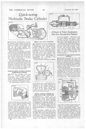
PATENT No. 514,030 shows a master hydraulic brake cylinder giving two degrees of pressure, one for bringing the shoes into contact, and a higher pressure for the actual braking. The patentee is the Hydraulic Brake Co., of Detroit, Michigan, U.S.A.
Referring to the drawing, the pedal pushes the rod carrying the large piston (1); this displaces the fluid which passes via the small central bore (2) and the space around the plug (3) to the space (5) whence it flows past a two-way valve (6) to the delivery pipe.
After this preliminary movement, the large piston (1) makes contact with the tube (2) and seals off the central bore; thereafter it moves as one with a second piston (4), and thus, by virtue of the smaller size of piston 4, a higher pressure is built up in the pipe-lines.
MODIFICATION TO WELL-KNOWN COMBUSTION SYSTEM
PATENT No. 513,906 comes from S. A. Adolphe Saurer, Arbon, Switzerland, and describes improvements in the design of oil-engine combustion systems, principally as applied to its well-known cell-in-piston type.
The improvements reside in the pro portions rather than in the form of the parts, and are directed towards obtaining a certain path of air flow. The drawing shows a pictorial view of a cut-away part of the piston crown, in which the tonic combustion chamber is located. What appears to be a piece of wire is described as the path taken by a particle of air; this arrives via an overhead valve and is intended to scour the whole surface of the chamber, and end in a central whirl. Fuel is injected radially from a central nozzle.
A32
SMALL TWO-UNIT TRACTOR AN agricultural tractor of small size is shown in patent No: 514,014 by J. McCollough, 1281, Caroline Street, Alameda, California, U.S.A. As will be seen from the drawing, the vehicle comprises two parts, a forward tractive unit, and a rear-wheeled portion upon which the driver's seat is placed. The two units are pivotally united by a central vertical column, and steering is accomplished by " bending" the vehicle about this centre.
All the driving mechanism is carried on the front unit, which travels on a single track, the controls, however, arc extended to the trailing portion by means of flexible cables. No mention is made of the engine power, but another drawing shows an air-cooled unit of the motorcycle type.
NOVEL SPRING DESIGN IN INJECTION-PUMP GOVERNOR
CENTRIFUGAL weights used for N..-,governors usually vary their effect as the square of the speed, and this behaviour often gives rise to problems in designing the opposing springs. A novel form of spring is one of the features of an injection-pump governor shown in patent No. 514,044 by La Precision Mecanique, 11, rue Vergniaud, Paris.
The centrifugal weights (6) tend, during rotation, to move a sleeve (5) to the right, this motion being transmitted to an arm (1) attached to the rack rod of the pump. The movement is opposed by a large spring (4) of which part is parallel, the remainder (3) being of increasing diameter. The larger coils are more flexible, and offer a light resistance at first, but further movement closes them up solid and transfers their duty to the stronger parallel coils.
Another feature is an extra spring (2) which is short enough to have a slight end play while the governor is stationary. This freedom finally disappears when the engine reaches idling speed, the object being to allow the pump to give an over-injection for starting purposes.
PROGRESS IN COAL-DUST-ENGINE DESIGN TNJECTION apparatus for use with 'pulverized fuel forms the subject of patent No. 514,229 from the Hanomag concern of Hannover-Linden, Germany. The aim is to eliminate the possibility of the coal dust being sprayed on to the cylinder walls, where it would adhere and foul the lubricant.
The drawing shows the combustion chamber (3), the entrance to which is controlled by a valve (1). The fuel is brought, either as a pure dust or mixed with air, to a chamber (5), which communicates via a valve (4) with an annular passage (6) . This passage• is pro vided with a number of small bores (2) leading to the combustion chamber.
On the compression stroke, valve 1 remains closed until the pressure has risen to about three atmospheres; it is then opened and the rush of air into the chamber extracts, as it goes, a charge of fuel from bores 2. The compression is then continued until self-ignition occurs. Regulation for quantity is controlled by the opening time of valve 4.