


An Anti-vibration Engine Mounting
Page 34
If you've noticed an error in this article please click here to report it so we can fix it.
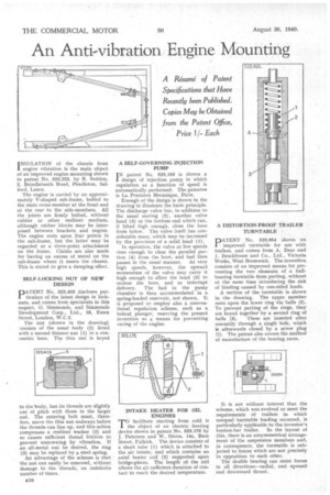
A Resume of Patent Specifications that Have Recently been Published. Copies May be Obtained from the Patent Office, Price 1iEach
I NSULATION of the chassis from engine vibration is the main object of an improved engine mounting shown in patent No. 523,223, by R. Seddon, 2, Brindleheath Road, Pendleton, Salford, Lancs.
The engine is carried by an approximately V-shaped sub-frame, bolted to the main cross-member at the front and at the rear to the side-members. All the joints are firmly bolted, without rubber or other resilient medium, although rubber blocks may be interposed between brackets and engine. The engine rests upon four points in the sub-frame, but the latter may be regarded as a • three-point attachment on the frame. Claims axe also made for having an excess of metal on the sub-frame where it meets the chassis. This is stated to give a damping effect.
SELF-LOCKING NUT OF NEW DESIGN
PATENT No. 523,403 discloses particulars of the latest design in locknuts, and comes from specialists in this respect, 0. Simmonds, and Simmonds Development Corp., Ltd., IS, Essex Street, London, W.C.2.
The nut (shown in the drawing) ..,onsists of the usual body (2) fitted with a second thinner nut (1) in a con:entric bore. The thin nut is keyed to the body, but its threads are slightly out of pitch with those in the larger nut. The entering bolt must, therefore, move the thin nut endways before the threads can line up, and this action compresses a resilient washer (3) and so causes sufficient thread friction to prevent unscrewing by vibration. If an all-metal nut be desired, the ring (3) may be replaced by a steel spring.
An advantage of the scheme is that the nut can easily be removed, without damage to the threads, an indefinite number of times. A SELF-GOVERNING INJECTION PUMP
IN patent No. 523,163 is shown a design of injection pump in which regulation as a function of speed is automatically performed. The patentee is La Precision Mecanique, Paris.
Enough of the design is shown in the drawing to illustrate the basic principle. The discharge valve has, in addition to the usual seating (2), another valve head (3) at the bottom end which can, if lifted high enough, close the bore from below. The valve itself has considerable mass, which may be increased by the provision of a solid head (1).
In operation, the valve at low speeds rises enough to clear the parallel portion (4) from the bore, and fuel then passes in the usual manner. At very high speeds, however, the upward momentum of the valve may carry it high enough to allow the head (3) to reclose the bore, and so interrupt delivery. The fuel in the pump chamber is then accommodated in a spring-loaded reservoir, not shown. It is proposed to employ also a conventional regulation scheme, such as a helical plunger, reserving the present invention as a means for preventing lacing of the engine.
INTAKE HEATER FOR OIL ENGINES facilitate starting from cold is the object of an electric heating device shown in patent No. 523,175 by J. Paterson and W., Shirra, 14a, Bute Street, Falkirk. The device consists of a short tube (1) which is attached to the air intake, and which contains an axial heater coil (2) supported upon bridge-pieces. The length of the coil allows the air sufficient duration of contact to reach the desired temperature.
A DISTORTION-PROOF TRAILER TURNTABLE PATENT No. 523,054 shows an improved turntable for use with trailers, and comes from A. Dear and J. Brockhouse and Co., Ltd., Victoria Works, West Bromwich. The invention consists of an improved means for preventing the two elements of a ballbearing turntable from parting, without at the same time introducing the risk of binding caused by one-sided loads.
A section of the turntable is shown in the drawing. The upper member rests upon the lower ring via balls (2). To prevent parting of the rings, they are keyed together by a second ring of balls (3). These are inserted after assembly through a single hole, which is afterwards closed by a screw plug (1). The patent also covers the method of manufacture of the bearing races.
It is not without interest that the scheme, which was evolved to meet the requirements of trailers in which unequal turntable loading occurred, is particularly applicable to the inventor's torsion-bar trailer. In the layout of this, there is an unsymmetrical arrangement of the suspension members and, in consequence, the turntable is subjected to forces which are not precisely in opposition to each other.
The double bearing can resist forces in all directions—radial, and upward and downward thrust.