


Patents Completed.
Page 34
If you've noticed an error in this article please click here to report it so we can fix it.
BRAKES.—Hall.-.--No. 13,910, dated 17th June, 1907.—According to this invention, two disc type brakes (A, B) are enclosed within dust-tight chambers (a, b). These chambers are cast integral with the differential casing (C) which is made i(1 two parts so that, when the top half, or section, is removed, the brakes and differential gear are exposed for inspection. Rings (al) are rigidly secured to the wall of the brake chambers, Further rings (a2) are interposed between the rings (al) ; the rings (at) being carried by hubs (a3) which are rigidly connected to one of the tubular elements (e, el). An operating lever (g) actuates the cams (I) so as to cause pressure plates (/1) to force the rings (al, at) together.
CHANGE SPEED MECHANISM.Heald.—No. 13,253, dated 7th June, 1907. —A driving shaft (a) is provided with bearings (al, a2) and it has keyed thereon four bevel wheels (c, d, e, :I) of varying diameters. Mounted on the shaft (6), which is directly, or indirectly, connected with the car axle, is a sleeve (f2) having fixed to it a bevel wheel (f1) which is adapted to engage with the bevel wheel (f) carried by the shaft (a), Sleeves (el, d2, c2), which carry bevel wheels (el, dl, c1) adapted to engage with pinions (e, d, e) carried by the shaft (a), are arranged on the sleeve (ft). This sleeve is provided with a sliding jaw clutch (n) connecting it with the casing (a) which carries the differential gear (p.). It will be seen that, by sliding any one of the sleeves (fl, e2, d2, et) and, with it, either of the bevel wheels (fi, c1, dl, el) into engagement with one of the bevel wheels carried by the shaft (a), a variable speed will be obtained.
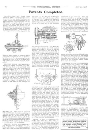
CHANGE SPEED MECHANISM.— The Wolseley Tool and Motor Car Co., 'Ltd., and Others.—No. 10,208, dated 3rd May, 1907.—The driving shaft comprises two parts (A, Al), the part (A) having a reduced portion (At) which enters a hole in the part (Al). Parallel with the shafts (A, A)) are other shafts (13, B1), the shaft (B) having a reduced end (b5) which enters a hole in the shaft (B1) so that the shafts may rotate independently. The shaft (Al) carries a bevel pinion (a) which meshes with a bevel wheel (c) carried by the differential. Mounted on the shaft (B1) is a bevel pinion (6) which meshes with a bevel wheel 1c1) also carried by the differential. A pinion (al) is mounted on the shaft (A) and it is adapted to gear with a spar wheel (bi) secured to the shaft (B). The pinion (al) is provided, at one end, with jaws (a2) which engage with jaws (a3) on the shaft (Al) so that, when the pinion (ca) is moved along the shaft (a) by means of the operating lever (m), the two shafts (A, Al) are locked together. A pinion (b2), which is adapted to gear with a spur wheel (a4) on the shaft Al),( is mounted on the shaft (B). The pinion (0) is provided with jaws (b3) which are adapted to engage with jaws (0) on the shaft (131) thereby locking the shafts (B, BI) together. The third, or lowest, speed is obtained by sliding the pinion (0) into mesh with the spur wheel (a4) the drive then being through the pinion (al), wheel (b1), shaft (13), pinion (0), wheel (a4), shaft (Al), and bevel gearing (a, c). To obtain the second speed the pinion (0) is moved out of mesh with the wheel (a4), and the clutch teeth (b3) are moved into engagement with the clutch teeth (b4). The first, or top, speed is obtained by sliding the clutch teeth 03) out of engagement with the clutch teeth (b4) without bringing the pinion (0) into mesh with the wheel (s4) or the clutch teeth (a:2) into, engagement with the clutch teeth (a3). The drive is thus brought direct from the shaft (A) through the shaft (Al) and bevel wheels (a, c), the shaft (13, B1) being idle.
DRAIN VALV E.—Patterson.--No. 11,435, dated 16th May, 1907.—This invention relates to automatic drain valves for draining steam cylinders and the like. The valve comprises a casing (8) which is screwed into the nozzle of an ordinary cock (/). The casing is provided with a valve seating (c) which is adapted to ac commodate a baT1 valve (a). This ball valve is carried by a spring ((1) which normally keeps the valve off its seating. A cylindrical sleeve (e), having a series of apertures (dz), surrounds the valve and its spring. This cylindrical sleeve is attached to a partition (f) in which holes (g) are provided. Upon admission of steam to the steam chest or cylinder to which the valve is attached the condensed water is forced by the steam down through the apertures (g) into the space (el), whence it passes out under the valve (a) and is expelled through the opening in the seating (c). Upon increasing the pressure of the steam the ball valve (a) is, after the expulsion of the condensed water, closed down upon its seat (c).
VARIABLE SPEED TRANSMISSION GEAR.—Smith and Another.—No. 7,092, dated 25th March, 1907.—The engine (A) is mounted on supports (B) which are adapted to slide in bearings (4) provided in the cross beams (C) of the chassis, A friction disc (F), which engages with a friction wheel (E) carried by the shaft (I), is arranged on the crankshaft. Springs (17) are interposed between the casing of the engine and a fixed part of the chassis. These springs tend to keep the friction disc (F) in contact with the friction wheel (E.). A pedal (Z) is mounted on a spindle (H) carrying cams (C), which engage with the supports (B) of the engine so that, when the pedal is depressed, the engine, with its friction disc (F), will slide in its bearings (4) so as to be free from the friction wheel (E). This friction wheel is free to slide on its shaft (I) so that it can be moved nearer to, or further from, the centre of the friction disc (F) and a variable speed obtained. This is effected by means of a triangular member (El) operated by suitable means. The shaft (I) carries a sprocket wheel (K), which transmits its motion by means of a chain to the differential (N) which, in turn, transmits rnotioa through the sprockets (0) to the sprockets (p) on the driving wheels.