


What Yorkshire does today. . ?
Page 54
Page 55
If you've noticed an error in this article please click here to report it so we can fix it.
BY R. D. CATER, AM I nst B E -fipp 'ICHARD PETTY, Yorkshire haulier-extraordinary, is a man Pb. who, when he thinks something special is needed, sits down and designs it. Then, unlike many others who do exactly the same thing, Richard sets to and builds the prototype. Such is the way things have gone with a steerable three-axle running gear which he recently designed and then one morning arrived at the works of W. P. Butterfield at Shipley, Yorks, asking the designers there: "What do you think of that?"
The running gear has been made almost entirely from parts that can be bought off the shelf from various vehicle makers and component makers. It is an independently air-sprung unit on which the second two axles are steerable through rack-andpinion steering boxes and a steering shaft linked through the fifthwheel kingpin. The degree of use which has been made of proprietary parts can be assessed by the fact that the steering shaft is driven through a Morris 1000 crown-wheel and pinion. And driving the crown wheel is a kingpin taken from a Hope antijack-knife device.
This unit is allowed to -pivot in the upper fifth-wheel rubbing plate and it is locked in the lead taper of the fifth wheel, transmitting the drive to the crown wheel. As the tractive unit turns in relation to the semi-trailer, the crown wheel and pinion rotates the steering shaft which in turn operates the rack-and-pinion units.
An interesting point in the design is that the geometry of the steering has been obtained simply by using standard Guy Wulfrunian steering arms. The variation for the angles at which the two axles must steer is gained by moving the rack-and-pinion units fore and aft on the assembly, so shortening or lengthening the effective length of the drag links.
From the steering arms outwards all the equipment is Guy Wulfrunian. The stub axles carry 10-stud hubs and disc brakes. On the prototype the fixed axles were of the same make and type, but instead of being linked to the steering gear, adjustable stops were fitted to allow fine adjustment of alignment.
Working in from the steering arms, the actual suspension units have been fabricated by Mr. Petty. They comprise double wishbones of unequal length which are linked to the stub assemblies and the main frame through conical rubber bushes. These last units were, in fact, specially designed and made for the job. Telescopic dampers are fitted and the suspension is by Dunlop Pneuride double convoluted bellows which are angled inwards 70 from the vertical. The main frame of the running gear is fabricated from rolled-steel channel and angle sections, and carried within this framework are the air-hydraulic packs that provide braking power to the caliper disc-brake units. My first reactions when seeing the unit were that there was too much to go wrong. I conveyed these thoughts to the Butterfield engineers and during the intervening weeks between that visit and the test, quite a bit of redesigning of the framework was carried out. Also during this period the newly designed rubber bushes for the wishbone units arrived and were fitted. These are so substantial as to almost eliminate trouble from that angle.
A large part of the time spent in tanker design is directed towards saving unladen weight. The action of the Petty suspension provides two avenues along which weight-saving exercises can be pursued. The first of these is reflected in the beautifully smooth ride that results from the design. The second is in the reduction of stresses transmitted through the tank shell during turning.
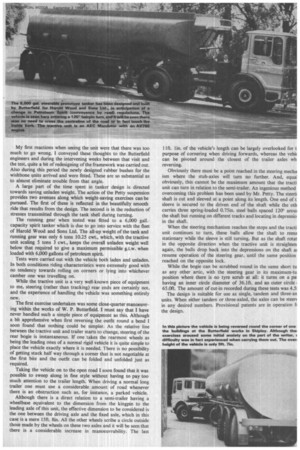
The running gear when tested was fitted to a 6,000 gall.capacity spirit tanker which is due to go into service with the fleet of Harold Wood and Sons Ltd. The all-up weight of the tank and running gear was only 6 tons 10.25 cwt., which, with the tractive unit scaling 5 tons 3 cwt., keeps the overall unladen weight well below that required to give a maximum permissible g.t.w. when loaded with 6,000 gallons of petroleum spirit.
Tests were carried out with the vehicle both laden and unladen. In both conditions riding characteristics were extremely good with no tendency towards rolling on corners or lying into whichever camber one was travelling on.
While the tractive unit is a very well-known piece of equipment to me, steering (rather than tracking) rear ends are certainly not, and the experience of handling the vehicle was something entirely new.
The first exercise undertaken was some close-quarter manoeuvring within the works of W. P. Butterfield. I must say that I have never handled such a simple piece of equipment as this. Although a bit apprehensive when first reversing the outfit round a bend I soon found that nothing could be simpler. As the relative line between the tractive unit and trailer starts to change, steering of the rear bogie is instantaneous. If one takes the rearmost wheels as being the leading ones of a normal rigid vehicle it is quite simple to place the vehicle exactly where it is needed. There is no possibility of getting stuck half way through a corner that is not negotiable at the first bite and the outfit can be folded and unfolded just as required.
Taking the vehicle on to the open road I soon found that it was possible to sweep along in fine style without having to pay too much attention to the trailer length. When driving a normal long trailer one must use a considerable amount of road whenever there is an obstruction such as, for instance, a parked vehicle.
Although there is a direct relation to a semi-trailer having a wheelbase equivalent to the dimension from the kingpin to the leading axle of this unit, the effective dimension to be considered is the one between the driving axle and the fixed axle, which in this case is a mere 15ft. 8in. All the other wheels scribe a circle outside those made by the wheels on these two axles and it will be seen that there is a considerable increase in manoeuvrability. The last I lft. lin. of the vehicle's length can be largely overlooked for t purpose of cornering when driving forwards, whereas the vein( can be pivoted around the closest of the trailer axles wh reversing.
Obviously there must be a point reached in the steering mecha ism where the stub-axles will turn no further. And, equal obviously, this cannot be the maximum amount that the tracti unit can turn in relation to the semi-trailer. An ingenious method overcoming this problem has been used by Mr. Petty. The steerii shaft is cut and sleeved at a point along its length. One end of t sleeve is secured to the driven end of the shaft while the oth carries three spring-loaded 0.75in. steel balls spaced 120° arotu the shaft but running on different tracks and locating in depressio in the shaft.
When the steering mechanism reaches the stops and the tracti unit continues to turn, these balls allow the shaft to rema stationary while the sleeve is still turning. But as the shaft rotat in the opposite direction when the tractive unit is straighten again, the balls drop back into the depressions on the shaft ai resume operation of the steering gear, until the same position reached on the opposite lock.
While the bogie can be scrubbed round in the same short tu as any other artic, with the steering gear in its maximum-tu position where there is no tyre scrub at all: it turns on a pal having an inner circle diameter of 36.1ft. and an outer circle I 65.0ft. The amount of cut-in recorded during these tests was 4.51 The design is suitable for use as single, tandem and three-ax units. When either tandem or three-wded, the axles can be steer( in any desired numbers. Provisional patents are in operation f4 the design.