


Automatic Fan Control
Page 80
If you've noticed an error in this article please click here to report it so we can fix it.
,k SCHEME in which the fan can be PI, engaged or freed by a temperatureresponsive unit is shown in patent No. .732,044, by Daimler-Benz AG., Stuttgart-Unterturkheim, Germany.
The drawing shows a complete cooling system with the added improvements. in the fan drive is a clutch (I); this may be of any desired type in place of the friction-disc pattern as illustrated. The clutch can be put into or out of action by a hydraulic piston in a cylinder (2) The hydraulic fluid, preferably engine oil, is controlled by a slide-valve (3) which either by-passes it or loads the
cylinder. The position of the slidevalve is determined by a thermostat bellows (4) located in the radiator return pipe.
The action is such that the fan is made to operate only when the temperature of the radiator outflow rises about the permitted value,
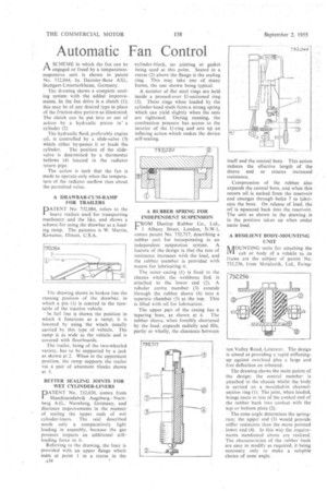
A DRAWBAR-CUM-RAMP FOR TRAILERS PATENT No. 732,084, refers to the heavy trailers used for transporting machinery and the like, and shows a scheme for using the drawbar as a loading ramp. The patentee is W. Martin, Kewanee, Illinois, U.S.A.
The drawing shows in broken line the running position of the drawbar, in which a pin (1) is centred in the turntable of the tractive vehicle.
' In full line is shown the position in which it functions as a ramp; it is lowered by using the winch usually carried by this type of .vehicle. The ramp is as wide as the vehicle and is covered with floorboards.
The trailer. being of the two-wheeled variety; has to he supported by a jack as shown at 2. When in the uppermost position, the ramp supports the trailer via a pair of abutment blocks shown at 3.
BETTER SEALING JOINTS FOR -WET CYLINDER-LINERS
PA TE N T No. 73Z020, comes from Maschinenfabrik Augsburg Nurnberg A.G.; Nurnberg, Germany, and discloses improvements in the manner of sealing the upper ends of wet cylinder-liners. The seal described needs only a comparatively light loading in assembly, .because the gas pressure imparts an additional selfloading force to it.
Referring to the drawing, the liner is provided with an upper flange which scats at point 1 in a recess in the A34
cylinder-block, no jointing or gasket being used at this point. Seated in a recess (2) above the flange is the sealing ring. This may take one of many forms, the one shown. being typical.
A number of flat steel rings are held inside a pressed-over U-sectioned ring (3). These rings when loaded by the cylinder-head studs form a strong spring which can yield slightly when the nuts are tightened. During running, the combustion pressure has access to the interior of the U-ring and sets up an inflating action -which makes the device self-sealing.
• A RUBBER SPRING FOR INDEPENDENT SUSPENSION E'ROM Dunlop Rubber Co., Ltd.; I Albany Street, London, N.W.1, comes patent No. 732,717, describing a rubber unit for incorporating in an independent suspension system. A feature of the design is that the rate of resistance increases with the load, and the rubber member is provided with means for lubricating. it.
• The outer casing (1) is fixed to the chassis whilst the wishbone link is attached to the lower end (2). 'A tubular centre member (3) extends through the rubber sleeve (4) into a separate chamber' (5) at the top. This is filled with oil for lubrication.
The upper part of the easing has a tapering bore, as shown at 6. The rubber sleeve, when foreibly shortened by the load, expands radially and fills, partly or wholly, the clearance between itself and the conical bore. This action reduces the effective length of the sleeve and so creates increased resistance.
Compression of the rubber also expands the central bore, and when this • occurs oil is sucked from the reservoir and emerges through holes 7 to lubricate the bore. On release of load, the oil is squeezed back into the reservoir. The unit as shown in the drawing is in the position taken up when under static load,
A RESILIENT BODY-MOUNTING
UNIT
ik 0 U NTIN G units for attaching the IVI cab or body of a Vehicle to its frame are the subject of patent No. 732,256, from Metalastik, Ltd., Eying ton Valley Road, Leicester. The design is aimed at providing a rapid stiffeningup against overload plus a large and free deflection on rebound.
The drawing shows the main points of the design; the central member is attached to the chassis whilst the body is carried on a moulded-in channelsection ring (1). The joint, when loaded, brings more or less of the conical end of the rubber bush into contact with the top. or bottom plate (2).
The cone angle determines the springrate; the .upper end (3) would provide stiffer resistance than the more pointed lower end (4). In this way the requirements mentioned above are realized. The characteristics of the rubber bush are easy to modify as required, it being necessary only to make a suitable choice of cone angle.