


ANOTHER TRACTOR DESIGN.
Page 22
If you've noticed an error in this article please click here to report it so we can fix it.
A Résumé of Recently Published Patent Specifications.
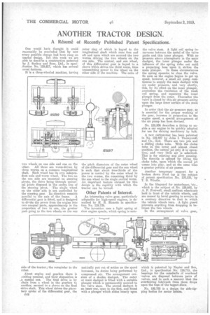
One would haie thought it could reasonably be concluded that by now every possible change had been rung on tractor design. Yet this week we are able to describe a construction patented by J. Ss,nliey and Sons, Ltd., in specification No. 129,817, which has several novel features.
It is a three-wheeled machine, having two wheels on one side and one on the other. AU three are worm-driven by three worms on a common longitudinal shaft. Etch wheel has its own independent axle and worm wheel. The two on the one side are 'mounted on steering pivots, the drive being through universal joints disposed in the centre line of the steering pivot. The single wheel on the other side is not controlled by the steering,gear. Its direction remains parallel to the axis of the frame. A differential gear is fitted, and is designed to divide the power from the engine into two unequal parts, approximately in the proportion of two to one, the greater part going to the two wheels on the one side of the tractor; the remainder to the other.
About engine and gearbox there is nothing unusual, and their disposition is ..a normal one. The final drive is by chain from a wheel in the gearbox to another, secured to a sleeve on the final drive shaft. This wheel drives the planetary spider of the differential gear, the • 018 outer ring of which is keyed to the longitudinal shaft which runs fore and aft and upon which are secured the two worms driving the two wheels on the one side. The central, and sun wheel, of this differential gear is keyed to a sleeve which drives the third worm, thus transmitting power to the wheel on the other side of the machine. The ratio of the pitch diameters of the outer wheel of the differential gear and-the sun wheel 'is such that about two-thirds of the power is Carried by the outer wheel to the two worms, the remaining third by the sun wheel to the single central worm. An important feature claimed for this design is the rapidity with which the tractor can be turned.
Other Patents of Interest.
An interesting valve gear, particularly adaptable for high-speed engines, is described by H. R. Ricardo in specification No. 129,729.
The invention uses a light spring at slow engine speeds, which spring is auto
matically put out of action as the speed increases, its duties being performed by compressed air. The arrangement consists of a double dashpot. The outer or main dashpot is fitted with a suitable plunger which is permanently secured to the valve stem. The second dashpot is an inner one, open to the first, and fitted with a plunger which slides loosely upon the valve stem. A light coil spring intervenes between the metal of the valve guide and this inner plunger. With no pressure above atmospheric in the main da.slipot, the inner plunger under the influence of the spring rides out until a projecting boss upon it strikes the • main plunger. In these circumstances the spring operates to close the valve. So soon as the engine begins to get up speed, however, a small air pump COMrnences to supply the main dashpot with air under pressure, and very shortly, this, by its effect on the inner plunger, overcomes the resistance of the weak coil spring, and separates the inner plunger from the outer. Thereafter the valve is closed by this air pressure acting upon the large inner surface of the main plunger.
In order that the air pressure may, as is essential for the proper working of the gear, increase in proportion to the engine speed, a special arrangement of the air pump has been devised.
No. 125,936 describes a fitting to enable a car engine to be quickly adapted for use for driving machinery by belt.
A new carburetter has been patented in No. 129,497 by John I. Thornycroft and Co., Ltd. There are two jets and a sliding choke tube. With the choke tube in the lower and almost closed position, the central jet only it in-operation; and very little air is admitted. This is for starting and slow Lunning. The throttle is opened by lifting the choke tube, upon which the second jet comes into play, and at the same time a greater portion of air passes.
• Another temporary support for a broken dawn Ford ear is the subject of patent specification No. 129,535, by T. B. Winclie.
In the lifeguard for motorbuses, 'etc., which is the subject of No. 129,662, by A. F. Fretwell, small resilient wheels are held in front of the vehicle wheels, and are caused by bevel gearing to revolve in a contrary direction to that in which the vehicle wheels turn. A light guard
pr i events anything from dropping n between the two wheels.
In the arrangement of valve gear,
which is patented by Napier and Son, Ltd., in specification No, 129,715, the bearings for the camshafts of overhead• valves are disposed between pairs of valves, and in such a manner that the overflowing lubricant from them drops upon the tops a the tappet discs.
No. 129,755 is a design for side-tipping bodies for motor lorries.