


MAKING BEST USE OF THE FORD.
Page 25
If you've noticed an error in this article please click here to report it so we can fix it.
Valuable Advice on Every Phase of Ford Transport which will Appeal to the Owner, Driver and Repairer.
605.—Choked Petrol Supply.
The symptoms of a choked petrol supply are generally easy enough to detect, but difficulty is sometimes experienced in locating the exact point at which the trouble has occurred. Very often it will be found that a block has occurred not in the sediment bulb or at the petrol strainer, but in the narrow neck above the stop cock. If there be still 'symptoms of shortage after removing and cleaning the strainer, a temporary expedient may be resorted to until it is convenient to remove the complete sediment-bulb assembly. By applying either a band or a foot pump to the delivery end of the petrol pipe and forcing a strong jet of air through the pipe the obstruction may be eased up from the neck of the sediment bulb.
There is one objection to this procedure (which is merely recommended for a case of extreme emergency), vie., the obstruction finds its way back to the tank and may return again at some equally inconvenient time. Probably the best thing is to remove the bulb there • and then. On a full tank or nearly full tank this will certainly occasion'some thought, but if it be borne in mind that the Ford sparking plug is also screwed to the same thread as the sediment bulb there need be little hesitation about removing the sediment bulb, for a sparking plug can be inserted in the hole left. A little dexterity in making the change over once the bulb is removed should prevent undue loss of petrol, but a bucket placed below the tankmay be found useful in the event of an extensive "spill."
606.—Attention Required by the Slow-speed-pedal Support.
A point that is apt to be overlooked— especially when relining the new-type bands with the detachable ears, leaving the transmission case in situ—is the condition of the slow-speed-pedal support and slow-speed connection.
Excessive wear of the slow-speedband lining is caused, nine times out of ten, by a worn pedal or pedal support, or by bad driving, in the tenth case, by the slow speed being incorrectly adjusted, the pedal fouling the floorboards. In all eases the wear is due to slipping which overheats the lining and eventually chars it.
It is a good plan *-1.ren relining the bands to clean with paraffin the pedals where they join the pedal shafts, and when the slow-speed connection is disconnected and the bands arc removed carefully to examine the pedal and its Support for wear_ As there is less actual movement of the slow-speed shaft to contract the band than of the reverse and brake shafts, it is essential that there should be no lost motion on the slow-speed shaft once the clutch has been diSengaged or excessive Wear of the lining will result.
should the pedal or the support show signs of being worn Concave Upon the notch faces, they should be renewed.
Providing that the pedal notch be not very badly worn and the hole for the slow-speed connection be still safe for further service, renewal of the pedal support will ensure satisfactory operation for a further period.
By a little manipulation and forcing the exhaust pipe down out of the way, the slow-speed pedal and shaft can be withdrawn and the support removed. It will generally be found that the bolt securing the support in position will remain stationary while the nut is run off, but the bolt head can just be reached by a socket wrench of the Walden Worcester type, while the bands are out of the case. The slowspeed connection, clevis and pin should also be inspected for wear and renewed if required.
Checking these items actually takes very little time, and should be included in the general relining routine, for the detection and renewal of worn pedals and supports obviates a subsequent relining in the near future.
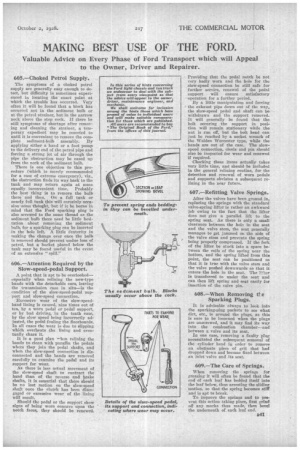
607.—Refitting Valve Springs.
After the valves have been ground in, replacing the springs with the standard valve-spring lifter is rather an awkward job owing to the fact that the lifter does not give a parallel lift to the spring seat. As there is only a small clearance between the hole in the seat and the valve stem, the seat generally manages to get jammed On the side of the valve stem and prevents the spring being properly compressed. If the fork of the lifter be stuck into a space between the coils of the spring near the bottom, and the spring lifted from this point, the seat can be positioned so that it is true with the valve stem and the valve pushed downwards so that it enters the hole in the seat. The 1!.r..er is transferred to under the seat and can then lift spring and seat easily for insertion of the valve pin.
608.—When Removing the Sparking Plugs.
It is advisable always to look into the sparking,-plug pockets to see what dirt, etc., is around the plugs, as this is sure to he loosened when the plugs are unscrewed, and it may find its way into the combustion chamber—and between a valve and its seat.
In one case, removing a faulty plug necessitated the subsequent removal of the cylinder head in order to remove an obstinate piece of grit that had dropped down and become fixed between an inlet valve and its seat.
-609.—The Care of Springs.
When removing the springs for greasing it will often be found that the end of each leaf has bedded itself into the leaf below, thus arresting the sliding motion, so that the spring becomes stiff and is apt to break.
To improve the springs and to prevent this action taking place, first grind eif any marks thus made, then bevel the underneath of each leaf end.