


A Power operated Clutch
Page 80
If you've noticed an error in this article please click here to report it so we can fix it.
DATENT No. 756,282 (F. Porsche,
Neckarsulmer Strassc 85, StuttgartZuffenhausen, Germany) gives details of a scheme for operating a vehicle clutch by power.
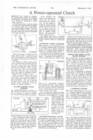
The drawing shows a general outline in which 1 is an engine-driven oil pump, 2 a control valve, and 3 the clutchoperating hydraulic cylinder. The control valve is linked to the gear !ever (4) and a little lost motion is permitted In all gear positions.
When the engine is idling, the oil pump delivers only a small flow and this is by-passed by a small duct across the pump, so that there is no action on the clutch.
An increase in engine speed pumps more oil which passes through the control valve and causes the hydraulic cylinder to engage the clutch, the gear still being in neutral. Upon moving the gear lever, the first lost-motion movement works the control valve and causes the clutch to disengage; further movement then engages a gear.
When the driver releases his hold on the gear lever, it moves through its lost motion and causes the clutch to engage gradually. The act of moving the gear lever from one speed to another always declutches as in the manner of manual operation, SUCTION-ASSISTED ROAD SWEEPER
AROAD-SWEEPING machine in which the brush action is assisted by air currents, is shown in patent No. 755,381 (K. Schorling, Davenstedter
Strasse 49, Hannover-Linden, Germany).
in the drawing, the rotary brush (1) is shown provided with a pressure nozzle (2) on the one side and a suction nozzle (3) on the other. The air pressure blows the material into the brush and the suction lifts it and conveys it into the body. A power-driven blower (4) is the motive unit for the air.
A34 Upon reaching the body, the air deposits the refuse into the bottom and returns for re-circulation. In dry weather it would be passed through a filter unit (5), but if the air be moist it can be returned directly through duct 6 without being filtered. The control for this is a flap valve (7).
The vehicle also carries a powerful magnet (8) for picking up the numerous ferrous objects found on present-day roads.
AUTOMATIC TAPPET ADJUSTER
TO maintain a valve mechanism in a properly adjusted state at all times is the object of a scheme shown in patent No. 756,263 (Eaton Manufacturing Co., Cleveland, Ohio, U.S.A.).
The push-rod in this scheme is made in two parts, freely screwed together at point 1. Joining the two members is a coiled torsion-spring (2) which urges them in an " unscrewing " direction, thus taking up all slack. This condition is suitable for the valve-opening stroke, , but on the closing stroke it is desirable to have a little slack in order to ensure certain seating of the valve.
This is achieved by slightly screwing the parts in a shortening direction on the downstroke of the push-rod. A coiled spring (3) grips the lower portion and if it is rotated will turn the rod. The slight rotation required is produced by end 4 of the gripping spring which, as it descends, slides in a slot in a stationary cam plate (5).
ALUMINIUM-COATED VALVES
CLA1MED to resist oxidation and the effects of leaded fuels, a new treatment for valves is disclosed in patent No. 754,592 (General Motors Corp., Detroit, Michigan, U.S.A.). The process consists of applying a thin layer of aluminium to the valve head.
There are two layers, the outer one being aluminium and the inner one the aluminium-base-metal alloy formed in the process. The outer layer is only 0.0015 in. and the inner one 0.001 in.
The coating is applied by first chemically cleaning the valve and then heating, fluxing and dipping in a bath of molten aluminium. After removal from the bath, the valve is re-fluxed and then vibrated to shake off surplus metal.
DEVICE FOR EASING HANDBRAKE RELEASE
IF a hand brake be fully applied, it often requires considerable physical effort to apply the little extra pull-on that is necessary to free the retaining pawl. A lever arrangement for easing the operation comes in patent No. 756,266 (J. Merrilees and Westinghouse Brake and Signal Co., Ltd., both of 82 York Way, London, N.1).
The lever arrangement is generally Conventional, as shown in the drawing, except that the toothed quadrant, instead of being rigidly fixed, is held against a cam (1) by a spring (2). It is this cam that is used to release the pawl; it is made in the form of a pedal which, when depressed by the driver, moves the quadrant a distance sufficient to free the pawl. There is thus no need to pull the brake on a little more.
A STEERING DAMPER
TO resist rapid shocks is the aim of a damper designed for incorporation in steering gear by -Daimler-Benz A.G., Stuttgart -Unterturkheim, Germany. The scheme is intended mainly for heavy vehicles, but is not limited to
such. The patent is numbered 756,518.
Referring to the drawing, the steering track-rod (1) is connected to a pair of small dash-pots (2) by means of bellcranks (3). These do not impede the comparatively slow steering movement, but resist rapid wobble sometimes occurring with independent suspension.