


BRAKING ON BOTH SIDES OF THE DRUM.
Page 76
If you've noticed an error in this article please click here to report it so we can fix it.
A Rgsuni6 of Recently Published Patent Specifications.
A1311AKE which acts on both the inside and the outside of a drum is shown in the specification of Ralph Henry Rosenberg, of New York, No. 246,820. An arm is fixed to the, nonrevolving axle sleeve and projects in a radial direction towards the periphery of the drum. To this arm is attached a member which carries two bosses at one end, and is pivoted to the radial arm at the other end. Through the two bosses on the pivoted member pass two pins that each support one of the brake shoes, as shown in the sectional view on the right. Both these pins are provided with eccentric parts which carry the brake shoes, the outer one being merely for adjustment for wear, whilst the inner one carries a lever, and is for the application of the brake.
It will be seen that as the eccentric draws the two shoes together the pivoted member can accommodate itself, so that the pressure on the inner and outer shoe must I.)e exactly even. The shoes, being mounted on the eccentric pins, are free to bear evenly along their whole surface against the brake drum. The specification claims as an advantage that no distortion of the drum takes place, and that as a large area of the drum is exposed to the air there is better radiation of any heat generated, also that more than one pair of shoes could be fitted.
It would seem to us that the short shoes and exposed drum would make conditions better for the drum, but -worse for the linings of the shoes.
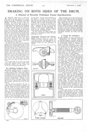
For Holding Gudgeon Pins.
ALFRED JOHN RILEY, in Specifica tion No. 258,696, shows a method of holding gudgeon pins. From the number of cylinders that are, even to-day, scored by gudgeon pins, one may conclude that at least some of the methods in use are far from satisfactory. Simple as the holding of such a pin may seem, it has proved one of those little troubles that have hardly been got over by our designers.
In the present invention the pin is drilled with a cross-hole, as shown on the left, which does not go right through the pin with its larger diameter, but stops short.and terminates in a smaller hole. A. spring-operated plunger is introduced, and is pressed flush with the pin whilst it is being introduced into the piston ; when the plunger comes Opposite a hole previously made in the piston boss it is projected by the spring, .am] the pin is secured from movement
of any kind. Another plan is shown on the right, in which a screw is 'fitted into the pin, and when in place is projected by means of the square part and a hollow key, so that its smaller part locks the phi by being wound down so that it engages the hole in the piston boss. Nothing is said regarding the locking of this screw, which might return to its original position, which would release the gudgeon pin.
In the opinion of some engine designers it is beneficial to allow the gudgeon pin to float..
Adjustable Rockers for Valves.
THE Triumph Cycle Co., Ltd., and
Frank Gordon Parnell describe in their specification, No. 258,697, an adjustable rocker for the operation of valves. The invention lies in the provision of a means of adjustment both in assembly and for wear. The rocker is of ordinary form excepting that the boss is larger than usual; and is split and provided with a clamping screw. An eccentric bush is fitted and has a hexagon head, so that it can be rotated to the desired position to give the necessary clearance between the rocker and the valve stem, and isithen clamped to prevent further movement between the bush and the rocker.
A Gauge for Cylinders.
CARL ZEISS, of Jena, Germany, in
specification No. 245,066, describes an internal calliper, or gauge, which can be used for general purposes, but should be particularly useful in gauging the bores of engine cylinders. It is well known that such gauges that have only two points are very, difficult to use with accuracy, owing to the virtual impossibility of ensuring the two measuring points being diametrically opposite to each other, as the slightest error in position will give a false reading.
• In the present invention there are four points in contact with the cylinder walls when in use. Two of thesepoints are fixed, and are only intended for steadying the instrument so that the two measuring points shall be diametrically opposite to each other, The two measuring points are formed on the ends of plungers that arc free to slide in the body of the instrument. The upper one shown has its lower end' ground flat and at right angles to its axis, whilst the lower one has its upper end flat, but at an angle to its axis.
A spring-actuated plunger passes through the stem of the instrument and presses a ball against the faces of the measuring plungers, so that it tends to force them apart, and in so doing brings them into contact with the cylinder walls. It will be seen that the two measuring plungers, and the ball that separates them, can slide so as to take up their correct nositiens in relation to the fixed points, without altering the position of the spring-operated plunger.
A dial and needle are provided to magnify the=movement of the snring plunger so that minute errors in a cylinder bore can easily be detected. It will be seen that the apparatus is of sturdy design and yet is compact and easy to handle. • ,