


Patents Completed.
Page 22
If you've noticed an error in this article please click here to report it so we can fix it.
Adjusting Wear In Brake Shoes. Vandervell Non-distributor Magneto. Roller Bearing Construction. Improved Sparking Plug.
Copies of complete specifications of the patents published on this page can be obtained from the Sales Branch, Patent Office, Holboim, W.C., at the cost of sixpence for each specification.
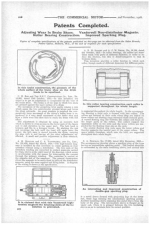
C. H. ROE and TELE R.E.T. Coxsaatuerrox CO., LTD., No. 14,483, dated 13th October, 1915.—In this invention the object is to get an adjustment to compensate for the wear of the brake shoes. The brake is Of the type in which two shoes are pressed against the inner surface of a drum.
The movement of the projecting lever partly rotates a cam which opens the two semi-circular pivoted levers and forces the shoes outwards. As great pressure is required the comparatively large movement of the driver's brake lever is reproduced in a very small movement of the brake shoe and after a little wear this shoe fails to reach the drum with full effect.
The adjustment is obtained by using an eccentric bolt which is shown in cross-section in the lower part of the figure and in end elevation in the upper part. The bolt -head is hexagon and fits in a hexagon recess. By slacking the nut and revolving the bolt until the head will again enter the recess; the bolt stem is moved towards the drum, carrying the shoe with it and leaving all the other adjustments mi. affected. A small and positive adjustment is thus obtained.
A. H. MIDGLEY and C. A. VANDERVELL AND CO., LTD,, No. 101,439, dated 4th March, 1916.—The high-tension magneto is modified by this invention to create ignition in four cylinders without using a distributor. The two ends of the cecondary winding are connected to contact segments carried by rings, shown at the right hand of the drawing, which rotate in synchronism with the means for interrupting the current through the primary winding. The condenser is,carriod at the opposite end of the aamature. The general construction allows the magneto to be easily fixed in place of the distributor magneto, using the same support and fixing holes. A diagrain of the wiring is shown in the specification. A. R. M. SANKEY and A. J. M. Sairrir, No. 14,156, dated 6th October, 1915.—In roller bearings, the rollers are sometimes made with parts of different diameter, in order to reduce the friction, but this is disadvantageous in that it weakens them.
This invention provides a roller bearing in which each roller, though made of different diameters for different parts, is supported throughout its whole length. In the accompanying drawing a fixed axle is formed with two collars. The rollers are reduced at their ends where they are seated on these collars and floating rings surround these reduced parts. A second floating ring lies between the collars and bears on the larger parts of the rollers. The collars support the uppermost roller at the ends and the lower rollers are suspended -by the floating rings also at the ends.
The central floating ring rests upon the lower rollers and thereby supports the central part of the upper rollers. The uppur rollers therefore, which take the load, are supported throughent their whole length.
S. A. NEWMAN, No. 17,330, dated 10th December, 1915.— The accompanying drawing shows a sparking plug of the typo having an intermediate sparking point. The central electrode is surrounded by the main insulating sleeve, and around this is a metal sleeve formed with projecting lugs at the lower end, these lugs forming the intermediate sparking points. Another insulating sleeve separateo this metal sleeve from the body of the plug. The intermediate sleeve is flanged at its upper end, where it is gripped between the two insulating sleeves so as to maintain it in its correct position.