


An Air-brake Control Valve
Page 58
If you've noticed an error in this article please click here to report it so we can fix it.
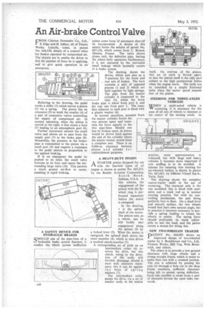
FROM Clayton Dewandre Co., Ltd., S. Edge and H. Jeffery, all of Titanic Works, Lincoln, come, in patent No. 664,530, details of a control valve for brakes operated by compressed air. The objects are to enable the driver to feel the amount of force he is applying, and to give quick operation in an emergency.
Referring to the drawing, the pedal works a slider (I) which moves a piston (2) via a spring. The piston has an extension (3) to work the smaller (4) of a pair of concentric valves controlling the supply of compressed air. In normal operation, when the piston is moved to the right, it first closes a bore (5) leading to an atmospheric port (6).
Further movement unseats the small valve and allows air to pass from the supply port (7) to the brake pipe (8). Meanwhile, the pressure in the brake' pipe is transmitted to the piston via a small port (9) and imparts a resistance to the pedal motion in proportion to the applied braking.
If in an emergency the pedal be pushed to its limit, the small valve bottoms in its bore and opens the.surrounding large valve (10). This permits a much greater air-flow to occur, resulting in rapid braking..
unless some form of automatic shut-off be incorporated. A device of this nature forms the subject of patent No. 667,126, which comes from C. Briand, Mantes, France. The valve shown closes only the defective pipe, leaving the others fully operative; furthermore, it is not operated by the inevitable small leakage which normally occurs in a brake system.
The drawing shows the device, which acts also as a T-junction for the front and
, rear sets of brakes. The bore contains a pair of opposed pistons (1 and 2) which are held together by light springs. The pipe from the master cylinder is connected to the inlet (3), whilst the front brake pipe is taken from port 4, and
the rear one from port 5. The inner face adjacent to each port is fitted with a plastic washer (6). In normal operation, pressure from the master cylinder forces the two pistons apart and transmits the force equally to the two pipe-lines. Should one line be broken open, its piston would be driven hard against the end of the cylinder where the plastic washer would form a complete seal. There is an 0.004-in, clearance between pistons an d cylinder f o r replenishment purposes.
A HEAVY-DUTY PINION
A STARTER pinion designed for use 1. with the heaviest types of oil engine is shown in patent No. 665,242, by the Bendix Aviation Corporation,
South Bend, Indiana, U.S.A. In this scheme, the engagement of the pinion with the flywheel ring is performed separately before the motor is energized.
In the drawing, is the splined
shaft of the motor. The pinion unit, as a whole, can be slid bodily into engagement along the splines (2) by a forked lever (3). When the motor is energized, the spline' shaft drives the outer member (4), which in turn drives a toothed clutch-member (5).
A corresponding set of teeth on an intermediate collar (6) receives the drive, but this clutch, owing to the direction of the teeth, will forcibly disengage should it meet with excessive resistance; this it can do against the force of spring washers (7).
The intermediate collar passes the drive, via a set of smaller teeth, to the pinion practice, some approximation is tolerated, but with large and heavy vehicles it becomes more important if tyre scuffing is to be avoided. A scheme for ensuring true steering for six-wheeled trailers is shown in patent No. 667,667, by Officine Viberti S.p.A., Turin, Italy.
The drawing shows the complete tractor-trailer outfit in the act a cornering. The rearmost axle is the one modified; this is fitted with stubaxles and a track rod as in normal steering practice, but with no controlling mechanism, the pair being perfectly free to float. On a dead level and smooth surface, the two wheels would find their own natural angle, but in practice it becomes necessary to provide. a spring loading to return the wheels to centre. The spring force should preferably be made adjustable to suit the load, and the patent covers a means for doing this.
'tself. On overrun of the pinion, this set of teeth iS forced apart, so that the pinion itself is the only part subject to the high acceleration forties when the engine starts. The teeth can be remeshed by a simple frictional helix when the •motor speed exceeds that of the pinion.
STEERING FOR THREE-AXLED VEHICLES
WHEN a multi-axled vehicle is cornering, it is necessary for the axes of all sets of wheels to intersect at the centre of the turning circle. In
NEW TWO-WHEELED TRAILER DATENT No. 666,093 shows an improved design of two-wheeled trailer by J. Brockhouse and Co., Ltd., Victoria Works, Hill Top, West Bromwich, and others.
The object is to provide a low ground clearance with large wheels and a strong straight frame, which is easier to make than one with a cranked portion. The aim is achieved by passing the axle (1) through a hole cut in the deep frame members, sufficient Clearance being left to permit spring deflection. Each side member is made from .a pair of channels having the open sides outwards.