


Patents Completed.
Page 26
If you've noticed an error in this article please click here to report it so we can fix it.
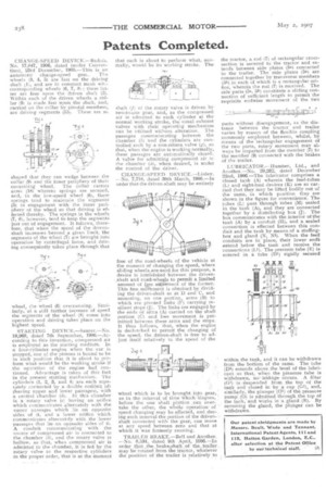
CHANGE-SPEED DEVICE.—Badois. No. 17,847, 1906, dated (under Convert. tion), 23rd December, 1905.—This is an automatic change-speed gni. The wheels (3, 4, 5) are fast on the driving shaft 01, and are in constant mesh wita corresponding wheels (6, 7, 8 ; these latter are free upon the driven shaft (2). Within each of the driven wheels a collar (9) is made fast upon the shaft, and, carried on the collar by pivotal members, are driving segments (15). These are se
shaped that they can wedge between the collar (9) and the inner periphery of their containing wheel. The collar carries arms (18) whereto springs are secured, and, in the low-speed wheel (6), these springs tend to maintain the segments (5) in engagement with the inner periphery of the wheel so that driving is effected thereby. The springs in the wheels (7, 8), however, tend to keep the segments just out of engagement. It follows, therefore, that when the speed of the drivenshaft increases beyond a given limit, the segments of the wheel (7) are brought into operation by centrifugal force, and driving consequently takes place through that
wheel, the wheel (6) overrunning. Similarly, at a still further increase of speed the segments of the wheel (8) come into operation and driving takes place on the highest speed.
STARTING DEVICE.—Saurer.—No. 19,969, dated 7th September, 1906.—According to this invention, compressed air is employed as the starting medium. In a. four-cylinder engine when the • car is stopped, one of the pistons is bound to be in such position that it is about to perform what would be the working stroke if the operation of the engine had continued. Advantage is taken of this, fact in the present starting mechanism. The cylinders (1, 2, 3, and 4) are each separately connected by a double coriduit (eP (having upper and lower passages), with a central chamber (h). In this chamber is a rotary valve (e) having an orifice which communicates alternately with the upper passages which lie on opposite sides of it, and a lower orifice which communicates alternately with the lower passages that lie on opposite sides of it. A conduit communicating with the source of compressed air is connected to the chamber (h), and the rotary valve is hollow, so that, when compressed air is admitted to the chamber, it is fed by the rotary valve to the 'respective cylinders in the proper order, that is at the moment
that each is about to perform what, normally, would be its working stroke. The
shaft (f) of the rotary valve is driven by two-to-one gear, and, as the compressed air is admitted to each cylinder at the normal working stroke, the usual exhaust valves with their operating mechanism can be utilised without alteration. The passages communicating between the chamber (h) and the cylinders are controlled each by a non-return valve (g), so that, when the engine is working normally, these passages are automatically closed. A valve for admitting compressed air to the chamber (h), when desired, is under the control of the driver.
CHANGE-SPEED D EVICE .—Li nley. —No. 7,718, dated 30th March, 1906.—In order that the driven-shaft may be entirely
free of the road-wheels of the vehicle at the moment of changing the speed, where sliding wheels.are used for this purpose, a device is introduced between the drivenshaft and road-wheels to permit a limited amount of flee nitiVernent of the former. This free mRetrient is obtained by dividing the driven-shaft as at D and C, and mounting, on one port)on, arms (B) to which are pivoted links (F) carrying resilient stops (D. The links are engaged by the ends of arms (A) carried on the shaft portion (C) and free movement is permitted between these arms and the stops. It thus follows, that, when the engine is declutched to permit the changing of the speed, the driven-shaft is free to adjust itself relatively to the speed of the wheel which is to be brought into gear, , as in the interval of time which 'elapses, , before the one shaft portion can overtake the other, the whole operation. of • speed changing may be effected, and during such interval the portion of the drivenshaft connected with the gear, can move at any speed between zero and that at which it was formerly running.
TRAILER BRAKE.—Bell and Another. —No. 8,534, dated 9th April, 1906.—In order that the ,brake:_shaft of tlle _trailer may be rotated from the tractor, whatever the position of the trailer is relatively to the tractor, a rod (7) of rectangular crosssection is secured to the tractor and extends between side plates (55) connected to the trailer. The side plates (5a) are connected together by transverse members (5b) in each of which is a rectangular orifice, wherein the rod (7) is received. The side parts (5a, 5b) constitute a sliding connection of sufficient length to permit the requisite endwise movement of the two
parts without disengagement, as the distance between the tractor and trailer varies by reason of the flexible coupling commonly employed between, whilst, by means of the rectangular engagement of the two parts, rotary movement may always be imparted from the member (7) to the member (9) connected with the brakes of the trailer.
LUBRICATOR.—Humber, Ltd., and Another.—No. 20,262, dated December 22nd, 1906.—The lubricator comprises a closed tank (A) wherein the feed-tubes (L) and sight-feed devices (K) are so carried that they may be lifted bodily out of the same, ia which position they are shown in the figure for convenience. The tubes (L) pass through tubes (M) sealed in the tank (A), and they are connected together by a distributing box (J). The box communicates with the interior of the tank (Al by a conduit (11), and a sealed connection is effected between this conduit and the tank by means of a stuffingbox and gland (N, NI). When the feed conduits are in place their lower ends extend below the tall and receive the connections (Li). The pressure tube (E) is entered in a tube (Di) rigidly secured
within the tank, and it can be withdrawn from the bottom of the same. The tube (DI) extends above the level of the lubricant so that, when the pressure tube is withdrawn, no leakage occurs. A filter (G2) is .suspended from the top of the tank and closed in by a cap (GI), and, similarly, the plunger (0.1) of the pressure pump (0) is admitted through the top of the tank, and works in a gland .(R). By removing the gland, the plunger can be withdrawn.