


A Morris Torsion-bar Suspension System
Page 36
If you've noticed an error in this article please click here to report it so we can fix it.
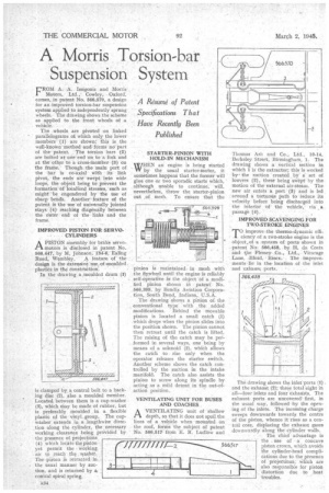
'ROM A. A. Issigonis and Morris Motors, Ltd.,'. Cowley, Oxford, comes, in patent No. 566,570, a design for an improved torsion-bar suspension system applied to independently sprung wheels, The drawing shows .the scheme as applied to the front wheels of a vehicle.
The .wheels are pivoted on linked parallelograms of, which only the lower members (1) are shown; this is the INell-knoWn method and' fOrrns no part of the patent. The torsion bars (2) are bolted at one end on to a link and at the other to a trosS-member (3) on the frame. Though the main part of the -bar is co-axial viiith its link pivot, • the ends are swept into wide loops, the object being to prevent the formation of 'localized strestes,• such as might be engendered by the use of sharp bendS. Another feature of the patent is the use of universally jointed stays (4) reaching diagonally between the duter ena of the• links and the frame.
IMPROVED PISTON FOR SERVOCYLINDBRS APISTON assembly for brake servomotors is disclosed in patent No. 566,447, by M, Johnson, 134-6, Ealing
Road, Wembley, feature of the design is the extensive 'use, of .nactulded plastits in ffte conitruction.
In the drawing a moulded drum (t) is clamped by a central bolt to a backing disc (2), also a moulded member. Located between them is a cup-washer (3), which may be made of rubber, but is preferably moulded in a flexible plastic of the vinyl group. The cupwasher extends in a .lengthwise dircc
tion along the cylinder, the 1 necessary working clearance being provided by the Presence of:projections, (4) which locate the piston yet permit the working air to reach the. washer. The piston is retracted in, the usual manner by suction, and is returned by a, conical spiral spring,
A34 STARTER-PINION WITH HOLD-IN MECHANISM
WHEN an engine is being started by the usual starter-motor, it sometinles happen§ that the former will give One or two sporadic starts which, although unable to continue, will, nevertheless, throw the starter-pinion out of mesh. To ensure that the -pinion is maintained in mesh with the flywheel until the engine is reliably self-operatiVe fa the object -Of a modified pinion shown hi • patent, No. 566,399, by Bendix Aviation Corporation, ,South Bend, Indiana, U.S.A.
The drawing 'shows a pinion of the conventional type: with the ,added modifications. Behind the Movable pinion is located a small catch (I) which drops when the pinion slides into the position shoWn. The pinion cannot then retreat until the catch is lifted. The raising of the catch may be performed. in several ways, one being by means of a solenoid (2), which allows the catch to rise only when the operator releases the starter switch. Another scheme shows the catch controlled by the suction in the intake manifold. The catch also assists the pinion to screw along its spindle by acting as a mild detent in the out-ofaction position.
VENTILATING UNIT FOR BUSES AND COACHES AVENTILATING unit of shallow depth, so that it does not spoil the lines of a vehicle when monnted on the roof, forms the subject of patent No. 566,517 from E. R. Ludlow and Thomas Ash and Co., Ltd., 10-14, Berkeley Street, Birmingham, I. The di-awing shows a Vertical section in which I is the extractor; this is worked bythe suction created by a set of louvres (2), these being swept by the motion of the external air-steam. The new air enters a port (S) and is led around a tortuous path to reduce its velocity before being discharged into the interior of the vehicle, via a passage (4).
TO improVe :the thermo-dynamic effi cidn.y of a two-stroke engine is the object.of a -system of .ports shown in patent No 566;458, by -H., da Costa and the Plessey Co„ Ltd.., Vicarage Lane, Ilfoid, Eiger. The improvements lie in the location of the inlet and exhaust ports. : The drawing shows the inlet:1)0ns (1) . and the exhaust (2); these total eight in all—four inlets and four exhausts, The exhaust ports are uncoveredl first, in the usual way, followed by the opening of the inlets. The incoming charge sweeps downwards towards the centre of the piston, whence it riseS as a central core, displacing the exhaust gases downwardly along the' cylinder walls.
• The chief advantage is the use of a concave piston crown, which avoids the cylinder-head complications due to the presence of projectiOnS; which are also responsible for piston distortion due to heat troubles.