


Steering Layout for Maximum Lock
Page 38
If you've noticed an error in this article please click here to report it so we can fix it.
A Risme of Patent Specifications that Have Recently Been Published
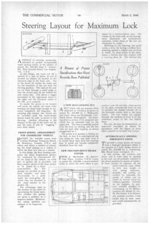
ADESIGN of steering mechanism, intended to permit exceptionally. small turning circles, is the subject of patent No. 515,974 from F. Ammer, 811, West Seventh Street, Los Angeles, Cal., U.S.A.
In this design, the track rod (3) is jointed to a pair of levers (2 and 4) pivoted on centres (1) located on the rearward edge of the front axle. One of the levers (4) carries the usual arm for the reception of the rod from the steering gearbox. The ends of the axle are set back through a small angle so that the swivel pins (5) are behind the axle centre line. This allows a bigger movement of the right-hand wheel to the right and the left-hand wheel to the left, as is required.
To enable the pivots to he located well inside the wheels, the inner roller hearings are made large. enough to surround completely the king-pins. By adopting this feature, the wheels can be swivelled until the brake-drums almost touch the axle, as shown in the drawing. Another advantage is the absence of the risk of the track rod (3) and the arms (2 and 4) " toggling " over dead centre.
FRONT-SPRING ARRANGEMENT FOR CHASSISLESS VEHICLE
PATENT No. 516,200 comes from London Passenger Transport Board, 55, Broadway, London, S.W.1, and others and shows a method of attaching the front springs of a vehicle in which the floor acts also as a chassis.
In this design, the floor framing comprises the usual longitudinal girders (1) reinforced by cross-bracers (2). At the front of the vehicle, an extra pair of girders (3) is provided, and these project ahead of the floor proper to be joined by a front cross-member (5). The springs are pivoted on this front member, and slope downwardly to a point under the cross-girder (4) where they are shackled in the usual manner to the girders (3).
The advantage rests in the absence of any need for upsweeping the frame mem bers, whether the springs are given a positive or a negative camber. Moreover, the riding qualities are claimedto he improved. A28 A NEW SELF-LOCKING NUT
ANUT which will not unscrew when subjected to vibration is shown in patent No. 515,929 by C. Whitcomhe and Guest, Keen and Nettlefolds, Ltd.. Heath Street, Birmingham. The drawing shows a section of the proposed nut,' which has an extended boss on .the upper end, The boss is partially parted from the body by slitting, and the free ends are bent after tapping, as shown exaggerated at 1.
The action is to produce a friction on the bolt, so that it is semi-tight ell the way along the bolt, and thus, even if it should slack back from the working ,face, it would not become completely detached from the bolt.
NEW FRICTION-SERVO BRAKE SYSTEM
FROM A. Martindale, 12, Queen's Gate Place, London, S.W.8, comes in patent No. 515,958, a power-assisted brake in which the servo effect is pro
duced by a friction-driven cam. The brakes on the front axle, in the arrangement illustrated, are hydraulically operated, whilst those at the rear are connected by cables.
Referring to the drawing, the pedal works a lever (2) having a helical face, abutting against a similar face on lever .5, which, by axial action of the faces, forces a friction disc into contact with a rotating plate (4). The frictinn disc carries a cam (3) and this, when moved by the plate. actuates the lever (1) and so operates the master cylinder (5) of the hydraulic system, that is, the front brakes. The rear brakes are applied through the medium of lever 5 _by' the rotational action of the two helical faces.
The cam (3) may be symmetrical, or somewhat one-sided, as shown, in accordance with the degree of servo effort required in forward and reverse.
• AUTOMATICALLY OPENING EMERGENCY EXITS TIO provide a ready means for escape 1 from a damaged passenger vehicle is the purpose of a body design shown in patent No, 515,950 by A. Armstrong, 265, Broad Lane, Liverpool, 11.
In this scheme, the windows and doors, and in some cases an opening in the roof, are all normally retained in the closed position by means of catches. If these catches be released, all the unitS would fly open, either by their own weight, or with spring assistance. Actually, the catches are worked by solenoids the circuit of which can be closed in several waysby collision-operated switches' on the bumpers, by mer"eury switches sensitive to overturning, or by thermocontacts for release by fire. By this Means, it is claimed, any possible accident would ensure that at least sonic exit would automatically be provided. 516 os
I
I