


ANOTHER GAS PRODUCER.
Page 34
If you've noticed an error in this article please click here to report it so we can fix it.
A Résumé of Recently Published Patents.
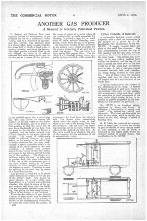
, L. Barrow and Cadbury Bros. have together devised an arrangement of gas producer for use on a commercial motor vehicle, and it is described in specification No. 137,708. The producer itself is a simple affair, being a plain cylinder, the lower half of which is linedwith refractory material, and forms the.furnace. The upper portion is almost filled by the fuel hopper, but there is an annular chamber left which serves as a reservoir for the gas as it comes off the producer.
In the available space, too, a 04311 of pipe fits. The pipe serves to convey the mixture of air and water to the underside of the firegrate, and it, is placed in that position so that the water and air may have the benefit of the heat from the gases to the end that the former is vaporized, and the latter warmed prior to their entrance to the space below the furnace. -The 'water is additionally helped to vaporize, however, by being drawn, on its passage to the coil of pipe to which reference has just been made, through a special vaporizer which is the subject of an earlier patent of the same inventors. A central tube projects almost to the bottom of the fuel funnel, and access to this tube is provided at the tap of the producer. The object is to facilitate poking the fuel. A poker may be pushed down this inner tube almost to the top of the incandescent part of the mass without having to be forced through the whole weight of the fuel in the hopper.or funnel. Provision is made for starting in the usual way by means of a-hand-operated fan.
The producer is intended to be placed eit immediately mmediately behind or by the side of the driver's seat. Gas leaves the upper chamber by a pipe which leads immediately to a vertical dust-collecting chamber, into which it enters at the top, and projects well down into the inside. The gas leaves this chamber again at the top, thus giving the dust every chance to deposit at the bottom of the chamber.
• From the dust-collector it goes through a range of pipes which may be disposed either round the roof of the vehicle, as shown on the accompanying illustration, or under the body, round the chassis. In C48 the range of pipes, at a point where it can conveniently be made accessible for cleaning, is placed a cage full of wood wool or other suitable cleansing compound, which filters the gas as it passes. An important feature of the invention is the mixing valve, which provides for the proper proportions of air and gas to enter the engine. The gas valve is a light spring-held poppet valve. The air valve is a cylindrical sliding valve, also partly spring-controlled, with means for adjustment by hand from the driver's seat. The former valve immediately closes when the engine stops, so that there is no risk of air flowing back into the producer. The air valve has taper= ing openings cut in its walls, which face others in the walls of the valve box. As the valve is slid in its chamber the area of the opening for the admission of air is automatically varied.
Other Patents of Interest.'
A carburetter fuel-feed system which dispenses with a float and accessories is the subject of a patent by G. H. La.nchester' the specification being No. 137,679. A supply chamber takes the place of the usual float chamber. One pipe communicates between the top of this chamber and the fuel tank, another runs from the bottom of the chamber to the same tank. The second one, however, is in one with a vertical tube within the chamber, and the top of the tube is about the same level as the fuel would be if the usual float mechanism were in use. A pair of valveless pumps intervene between tank and chamber, one pump being situated in each pipe line. One of them keeps the chamber supplied with fuel, the other draws off the surplus fuel as it tops the level of the inside tube.
A spring suspension is the subject of No. 137,661, by G.. B. Dorey. A system of levers applied to each axle works in conjunction with pairs of coil springs, the arrangement, being such that, while the resistance to small movements of the axle, under slight shocks, is hysv, it increases in greater proportion to the load. Means for lubrication are provided.
No. 137,776 is an American patent, registered by Feeny and Feeny. It describes a construction of spring road wheel. The spokes are hollow and telescopic. The inner hub transmits the drive to the outer, which is rigidly connected to the rim, through a series of floating links.
G. E. Lillie has patented an arrangement of speed gear, in which the change of gear is effected in every case by means of cone clutches, a nest of which is mounted on the engine shaft, where the ordinary clutch is usually found. The specification is No. 137,783.