


A New Fuel Pump
Page 68
If you've noticed an error in this article please click here to report it so we can fix it.
A Resume of Recently Published Patent Specifications
DESCRIBED in patent No. 391,593, by Bryce, Ltd., Kelvin Works, Rackbridge, Surrey, is a fuel pump for compression-ignition engines—it is of the type in which a constant stroke is imparted to a plunger by a cam, the variation of the amount of fuel injected to the engine being accomplished by allowing a certain quantity to return to the tank by opening a relief valve at the upper part of the stroke.
The cylinder in which the plunger works can be rotated by means of a rack (25) which engages with pinion teeth on the cylinder. The rotation of the cylinder brings into operation crossholes near the upper end of the plunger which permit a certain percentage of the fuel to escape when required.
A Krupp Refuse Body.
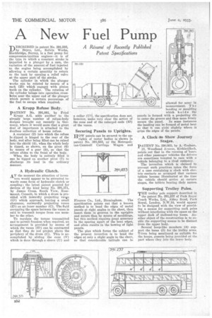
PATENT No. 391,081, by Fried Krupp A.G. adds another to the already large number of refuse-body designs brought out recently in Germany, where it would seem that a great deal of importance is attached to the dustless collection of house refuse.
A container (2) into which the refuse is -tipped is hinged to the rear of the body, and after being filled can be raised into the shield (4), when the whole body is tipped, as shown, on the pivot (6) by means of a gear (8), so that the refuse slides to the front of the body.
When the body is entirely filled it can be tipped on another pivot (7) to discharge its load in the ordinary manner.
A Hydraulic Clutch.
AT the moment the attention of inven tors would appear to be attracted towards some form of hydraulic clutch or coupling; the latest patent granted for devices of the kind being No. 391,371, by James Cross. South View, Rosemount, Consett, in which a drum is provided with inwardly projecting vanes (Gl) which approach, leaving a small clearance, outwardly projecting vanes (El) on an inner member (C). The fluid occupying the space between the vanes is said to transmit torque from one member to the other.
To regulate the torque transmitted and to permit freedom when required, an arrangement is provided by means of which the vanes (El) can be contracted so that they do not project above the periphery of the drum (C). This is accomplished by sliding the cone (V) which is done through a sleeve (U) and a collar (V), the specification does not, however, make very clear the action of the cone and of the enlarged ends (ES) of the vanes.
Securing Panels to Uprights.
HOW panels can be secured to the uprights of motor bodies is shown in patent No. 391,633, oy the Metropolitan-Cammelt Carriage Wagon• and Fit ance Co., Ltd., Birmingham. The specification points out that a known method is to bend the edges of metal panels at right angles to the sheet, then insert them in grooves in the uprights and secure then by means of mouldings, but this•method requires great accuracy in the spacing apart of the bent edges, and often results in the bowing of light panels.
The plan which forms the subject of the present invention is to bend the edges at only a slight angle to the sheet, so that considerable latitude can be allowed for error in measurement. T h e bending or moulding which holds the panels is formed with a projecting rib to enter the groove and thus more firmly secure the panel. In some instances the beading can be formed of metal bent so that it can yield slightly where it grips the edges of the panels.
A Clock to Show Journey Stages.
PATENT No. 390,665, by A. Graham,
18, Woodhead Avenue, Kirkintilloch, points out that in the running of buses and other passenger vehicles the drivers are sometimes tempted to race with a vehicle belonging to a rival company.
The invention which is "claimed to prevent such practices takes the form of a case containing a clock with electric contacts so arranged that various tablets become illuminated at the time the vehicle should arrive at certain stages, the tablets bearing their names.
Supporting Trolley Poles.
THE trolley pole support described in
the patent No. 391,237 of Park Royal Coach Works, Ltd., Abbey Road, Park Royal, London, N.W.10, would appear ta be designed with the view of providing a means for supporting such poles without interfering with the space on the upper deck of enclosed-top buses. Another object of the construction is to enable the supporting means to be distinct from the upper body.
Several hoop-like members (4) support the bases (3) for the trolley arms, T-iron being mentioned as suitable fot the hoops, gussets being provided at the part where they join the lower body.