


Silent-,third A Risvme of Recently Pub GEARBOX fished Patent Specifications
Page 66
If you've noticed an error in this article please click here to report it so we can fix it.
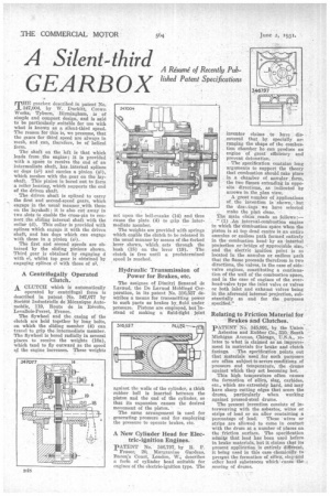
TUBHE gearbox described in patent No. 347,004, by W. Duckitt, Crown Works,: Tyburn, Birmingham, is et simple and compact design, and is said to be particularly, suitable for use with what is known as a silent-third speed. The reason for this is, we presume, that the gears for third speed are always in mesh, and can, therefore, be of helical The shaft on the "left is that which leads from ,the engine; it is provided with a space to receive the end of an intermediate shaft, has .internal splines or dogs (a3) and carries a pinion (al), which meshes with the gear on the layshaft. This pinion is bored out to form a roller ,bearing, which supports the end of the driven shaft.
The driven shaft is splined to carry the first and second-speed gears, which engage in the usual manner with thote on the layshaft ; it is also cut away in two slots to enable the cross-pin to connect :the sliding internal shaft with the collar (d). This collar is provided with splines which engage it with the driven shaft, and has dogs which can engage with those in a pinion (el).
The first and second speeds are obtained by the sliding Pinions shown. Third gear is obtained by engaging d with el, whilst top gear is obtained by engaging splines el with those of a3.
A Centrifugally Operated Clutch, A CLUTCH which is automatically
operated by centrifugal force is described in patent No. 347,077 by Societe Industrielle de Mecanique Automobile, 119, Route de la Revolte, Levallois-Perret, France.
The flywheel and the casing of the clutch are held together by long bolts, on which the sliding member (4) can travel to grip the intermediate member. The flywheel is bored radially in several places to "receive the weights (10a), which tend to fly outward as the speed qf the engine increases. These weights net upon the bell-cranks (14) and thus cause the plate (4) to grip the intermediate member.
The weights are provided with springs which enable the clutch to be released in the usual manner by means of the forked lever shown, which acts through the bush (15) on the lever (19). The clutch is free until a predetermined speed is reached.
Hydraulic Transmission of Power for Brakes, etc.
The assignee of Dimitri Sensaud de Lavaud, the De Lavaud Holding4 Corporation, in its patent No. 316,557 describes a means for transmitting power to such parts as brakes by, fluid under pressure. Pistons are employed, but 'instead of making a fluid-tight joint
against the walls of the cylinder, a thick rubber ball is inserted between the piston and the end of the cylinder, so that its expansion causes the desired movement of the piston.
The same arrangement is used for generating pressure and for employing the pressure to operate brakes, etc.
A New Cylinder Head for Electric-ignition Engines.
PATENT No. 346,797, by R. P.
Fraser, 20, Alargravine Gardens, Baron's Court, London, W.; describes a form of cylinder bead suitable for engines of the electric-ignition type. The
inventor claims to have dis,covered that by specially arranging the shape of the combustion chamber he can produce an engine of great efficiency and prevent detonation. ,
• The specification contains long arguments to support the theory that combustion should take place in a chamber . of annular ,.form, the two flames extending in opposite directions, as .indicated by arrows in the plan view.
A great number of applications of _ the invention is shown, but the drawings We have selected , make the plan clear.
The main claim reads as follows:—
" (1) An internal-combustion engine in which the combustion space when the piston is at top dead centre is an entire annulus or endless path formed entirely in the combustion head by an interhal projection or bridge of appreciable size, ' and the electric ignition point is so located in the annulus or endless path that the flame proceeds therefrom in two direCtions, the valves, in the case of sidevalve engines, constituting a continuation of the wall of the combustion space, and in the case of engines of the overhead-valve type the inlet valve or valves or both inlet and exhaust valves being in the aforesaid internal projection, substantially as and for the purposes specified." ..
Relating to Prktion Material for Brakes and Clutches.
pATENT No. 345,991, by the Union Asbestos and Rubber Co., 310, South Michigan Avenue, Chicago, U.S.A, relates to what is claimed as'an improvement in materials for brake and clutch facings. The specification points out that Materials used ;for such purposes are often subject to severe conditions of pressure and temperature,.the drums against which they act becoming hot.
• This high • temperature often causes the formation of silica, slag, carbides, etc., which are extreniely hard, and may have sharp cutting edges that score the drums, particularly when working against pressed-steel drums.
The present invention consists of interweaving with the asbestos, wires or strips of lead or an alloy containing a
percentage of lead. These • wires or strips are allowed to come in contact with the drum at a number of places on the friction surface. The specification admits that lead has been used before in brake materials, but it claims that its present application is entirely different, it being used in this case chemically to prevent the formation of silica, slag awl other hard sUbstances which cause' the scoring of drums.