 1
1 2
2 3
3 4
4 5
5 6
6 7
7 8
8 9
9 10
10 11
11 12
12 13
13 14
14 15
15 16
16 17
17 18
18 19
19 20
20 21
21 22
22 23
23 24
24 25
25 26
26 27
27 28
28 29
29 30
30 31
31 32
32 33
33 34
34 35
35 36
36 37
37 38
38 39
39 40
40 41
41 42
42 43
43 44
44 45
45 46
46 47
47 48
48 49
49 50
50 51
51 52
52 53
53 54
54 55
55 56
56 57
57 58
58 59
59 60
60 61
61 62
62 63
63 64
64 65
65 66
66 67
67 68
68 69
69 70
70 71
71 72
72 73
73 74
74 75
75 76
76 77
77 78
78 79
79 80
80 81
81 82
82 83
83 84
84 85
85 86
86 87
87 88
88 89
89 90
90 91
91 92
92 93
93 94
94 95
95 96
96 97
97 98
98 99
99 100
100 101
101 102
102 103
103 104
104 105
105 106
106 107
107 108
108 109
109 110
110 111
111 112
112 113
113 114
114 115
115 116
116 117
117 118
118 119
119 120
120 121
121 122
122 123
123 124
124 125
125 126
126 127
127 128
128 129
129 130
130 131
131 132
132 133
133 134
134 135
135 136
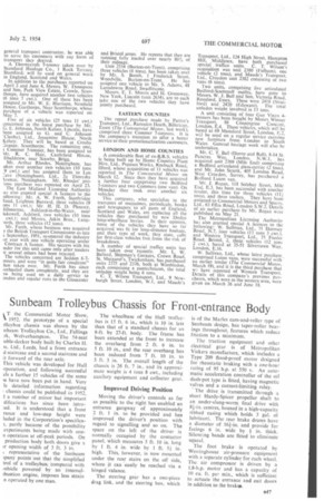
136 Sunbeam Trolleybus Chassis for Front-entrance Body
Page 93
If you've noticed an error in this article please click here to report it so we can fix it.
CT the Commercial Motor Show, 1952, the prototype of a special Aleybus chassis was shown by the nbeam Trolleybus Co., Ltd., Fallings
.rk, Wolverhampton. The 54-seat uble-decker body built by Charles H. se, Ltd., Leeds, had a front entrance d staircase and a second staircase and it forward of the rear axle.
This vehicle was developed for Hull .rporation, and following successful als a further 15 vehicles of the same ie have now been put in hand. Very le detailed information regarding : chassis could be published in 1952, i a number of minor but important difications has since been introaid. It is understood that a front rance and low-step height were luded in the Corporation's specifica1, partly because of the possibility experiments being made with mien operation at off-peak periods. On production body both doors give a ir opening width of 3 ft. 3 in.
representative of the Sunbeam tpany points out that the simplified trol of a trolleybus, compared with mhiele powered by an internalibustion engine, imposes less strain n operated by one man. The wheelbase of the Hull trolleybus is 15 ft. 6 in., which is 10 in. less than that of a standard chassis for an 8-ft. by 27-ft. body. The frame has been extended at the front to increase the overhang from 2 ft. 6 in. to 5 ft. 10 in., and the rear overhang has been reduced from 7 ft. 10 in. to 5 ft. 3 in. The overall length of the chassis is 26 ft. 7 in., and its approximate weight is 4 tons 8 cwt., including auxilary equipment and collector gear.
Improved Driving Position Moving the driver's controls as far as possible to the right has enabled an entrance gangway of approximately 2 ft. 1 in. to be provided and has improved the driver's position with regard to signalling and so on. The space on the left of the driver is normally occupied by the contactor panel, which measures 3 ft. 10 in. long by 1 ft. 4 in. wide by 1 ft. 51 in. high. This, however, is now mounted under the rear stairs on the off side, where it can 'easily be reached via a hinged valance.
The steering gear has a one-piece drag link, and the steering box, which is of the Marles cam-and-roller type of Sunbeam design, has taper-roller bearings throughout, features which reduce friction to a minimum.
The traction equipment and other electrical gear is of Metropolitan Vickers manufacture, which includes a Type 209 flood-proof motor designed for rheostatic braking with a one-hour rating of 95 h.p. at 550 v. An automatic acceleration controller of the oil dash-pot type is fitted, having magnetic valves and a current-limiting relay.
The drive is transmitted through a short Hardy-Spicer propeller shaft to an under-slung-worm final drive with 8l-in. centres, housed in a high-capacity ribbed casing which holds 3 gal. of lubricant. The rear brake drums have a diameter of 161-in. and provide for
facings 6 in. wide by in. thick. Silencing bands are fitted to eliminate squeal.
The foot brake is operated by Westinghouse air-pressure equipment with a separate cylinder for each wheel. The air compressor is driven by a 1.8-h.p. motor and has a capacity of 10 Cu. ft. per min., which is sufficient to actuate the entrance and exit doors in addition to the brake'.