 1
1 2
2 3
3 4
4 5
5 6
6 7
7 8
8 9
9 10
10 11
11 12
12 13
13 14
14 15
15 16
16 17
17 18
18 19
19 20
20 21
21 22
22 23
23 24
24 25
25 26
26 27
27 28
28 29
29 30
30 31
31 32
32 33
33 34
34 35
35 36
36 37
37 38
38 39
39 40
40 41
41 42
42 43
43 44
44 45
45 46
46 47
47 48
48 49
49 50
50 51
51 52
52 53
53 54
54 55
55 56
56 57
57 58
58 59
59 60
60 61
61 62
62 63
63 64
64 65
65 66
66 67
67 68
68 69
69 70
70 71
71 72
72 73
73 74
74 75
75 76
76 77
77 78
78 79
79 80
80 81
81 82
82 83
83 84
84 85
85 86
86 87
87 88
88 89
89 90
90 91
91 92
92 93
93 94
94 95
95 96
96 97
97 98
98 99
99 100
100 101
101 102
102 103
103 104
104 105
105 106
106 107
107 108
108 109
109 110
110 111
111 112
112 113
113 114
114 115
115 116
116 117
117 118
118 119
119 120
120 121
121 122
122 123
123 124
124 125
125 126
126 127
127 128
128 129
129 130
130 131
131 132
132 133
133 134
134 135
135 136
136 An Inertia Starter
Page 100
If you've noticed an error in this article please click here to report it so we can fix it.
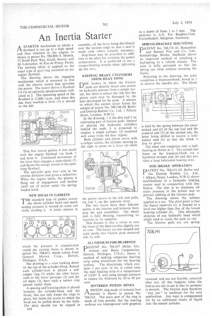
ASTARTER mechanism in which a flywheel is run up to a high speed and then clutched to the engine, is shown in patent No. 708,808 (J. Morris, 52 Ewell Park Way, Ewell, Surrey, and M. Leboucher, 46 Rue de Prony, Paris). The starting effort is applied to the usual type of gear-ring mounted on the engine flywheel.
The drawing shows the engaging mechanism which is mounted in line with the electric motor that provides the power. The motor drives a flywheel (1) via an epicyclic speed-increaser indicated at 2. The operating speed of the flywheel is 12,000 r.p.m., and when this has been reached a lever (3) is moved to the left.
This first moves pinion 4 into mest with the engine flywheel via hook 5 and lever 6. Continued movement of the lever then engages a cone-clutch (7) and draws the energy stored in the spinning flywheel.
The epicyclic gear now acts in the reverse direction and gives a reduction. When the engine starts, the pinion is flung out of engagement and latches itself out of action under the springloaded hook.
NEW IDEAS IN GASKETS THE standard type of gasket covers
the whole cylinder head and much sealing pressure is wasted on areas not really needing it. A better scheme in which the pressure is concentrated round the various bores is shown in patent No. 708,455, which comes from General Motors Corp., Detroit, Michigan, U.S.A.
The drawing is a view looking down on the top of the cylinder-block. Round each cylinder-bore is placed a soft copper ring (1) whilst the other bores, such as the water passages (2) and the oil ducts (3), have each a rubber ring placed round them.
A spacing and locating plate is placed between the cylinder-head and the block; this not only keeps the rings in place, but limits the extent to which the head can be pulled down by the bolts. The plate should not be nipped in B54 assembly, all the force being distributed over the various rings so that a seal is made only where actually necessary.
Stop-faces may be provided in addition to the plate for arresting the gasket compression. It is preferred to use a torque-limiting wrench when tightening up the nuts.
KEEPING BRAKE CYLINDERS FROM HEAT ZONE
D1SC brakes, in which the friction pads are directly thrust into action by hydraulic pistons, form a simple layout, but there is always the risk that the piston seals may be damaged by the heat developed on the pads. A scheme in which this cannot occur forms the subject of patent No. 708,748 (H. Butler and Dunlop Rubber Co., Ltd., 1 Albany Street, London, N.W.1).
In the drawing, 1 is the disc and 2 an embracing pair of friction pads. Instead of placing the hydraulic cylinders behind the pads, it is proposed to employ a single cylinder (3) mounted well away from the heat region.
Both cylinder and piston move with a caliper action, the cylinder moving to the right to press on a lever (4) while the piston moves to the left and pulls, via rod 5, on the opposite lever.
The two levers have their fulcrum points at the bottom and between them grip the pad assemblies. The whole unit is fully floating, transmitting no reaction to its supports.
This feature is also a virtue in case the faces of the discs revolve slightly out of true. The levers are star-shaped and each works two friction pads mounted side by side.
ALUMINIUM FOR BEARINGS
PATENT No. 708,107 (Bohn Aluminum and Brass Corporation, Detroit, Michigan, U.S.A.) shows a method of making composite bearing strip using aluminium for the bearing surface. The aluminium, which contains 2 per cent, of tin, is rolled onto the steel backing strip at a temperature of 1,030° F, and using enough pressure to reduce the thickness by 30 to 40 per cent.
SINTERED PISTON RINGS
APISTON ring made of sintered iron powder is shown in patent No. 708,562. The main part of the ring is made of iron powder, but the wearing surfaces are impregnated with graphite
to a depth of from 1 to 2 mm. The patentee is A.G. Fur Bergbau-UndHuttenbedarf, Salzgitter, Germany.
SPRING-SHACKLE MOUNTING
PATENT No. 708,576 (E. Hampshire and Samuel Fox and Co., Ltd., Stocksbridge Works, Sheffield) shows an improved method of attaching a leaf-spring to a vehicle chassis. The joint is fully universal so that the spring can twist without stressing the frame.
Referring to the drawing, the joint comprises a trunnion-block, bored at 1 to receive the shackle pin. The block is held by the spring between the swan necked end (2) of the top leaf and the cranked end (3) of the second one, the latter being drilled to receive a lock nutted stud (4) so that the block is free to pivot.
The other end comprises only a halfbearing as shown at S. The second leaf bears on the trunnion-block via a hardened arcuate pad (6) and this provides a large lubricated bearing area.
DISC-BRAKE OPERATION
PATENT No. 708,141 (H. Butler and the Dunlop Rubber Co., Ltd., 1 Albany Street, London, N.W.1) shows modifications to a hydraulic braking system used in conjunction with disc brakes. The aim is to eliminate all static pressure in the system and so prevent rubbing of the friction pads.
The drawing shows the scheme applied to a car. The chief point is that the liquid reservoir (1) is located at a level not higher than that of the lowest braking cylinder (2). This effectually disposes of any hydraulic head which might tend to cause the pads to rub.
The friction pads are not spring returned, and are not forcibly retracted after use; all that happens when the brakes are not in use is that no pressure is present. The friction pads therefore "stay put" in readiness for the next application. Any wear is compensated for by an additional intake of liquid into the master cylinder.