


Hydraulic Braking with Pressure Accumulators
Page 34
If you've noticed an error in this article please click here to report it so we can fix it.
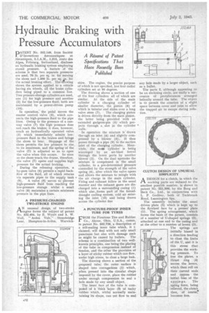
DATENT No. 552,149, from Societ4 1 D'Inventions Aeronautiques et .Mecaniques. S.I.A.M., 1,315, routa des Alpes, Fribourg, Switzerland, discloses an hydraulic braking system employing stored pressure. A feature of the scheme is that two separate pressures are used, 70 lb. per sq. in. for moving the shoes and 1,400 lb. per sq. in. for the actual braking effort. The drawing shows the system applied to a vehicle having six wheels, all the brake cylinders being piped to a common line. Two pressure-storage cylinders are used, one (1) for high pressure and another (2) for the low-pressure fluid; both are maintained by a power-driven pump (10).
In operation, the pedal moves the master control valve (3), which connects the high-pressure fluid to the pipe lines. Owing to the presence of a oneway valve (7) the high pressure does not. reach the brakes; it does, however, reach an hydraulically operated valve (5) which immediately admits lowpressure fluid to the brakes and brings the shoes to bear. Stoppage of the shoes permits the low pressure to rise to its maximum, and the springof the valve (7) is adjusted so as to open the valve when this occurs. So soon as the shoes touch the drums, therefore, the valve (7) opens and supplies high pressure for the actual braking.
During the releasing operation, a by-pass valve (6) permits a rapid back flowof the fluid, all of which returns via separate pipes to the supply tank (9). A valve (4) serves to prevent high-pressure fluid from reachirg the low-pressure storage whilst a small valve (8) maintains a certain minimum pressure in the pipe lines.
A PRESSURE-CHARGED TWO-STROKE ENGINE
AN unusual design of two-stroke engine forms the subject of patent No. 552,404, by E. Wyatt and A. W. Wall, "Arden Vale," Stonebridge Lane, Hampton-in-Arden, Warwick
shire. The engine, the precise purpose of which is not specified, ha S four radial cylinders set at 90 degrees.
The drawing shows a section of one of the four cylinders all of which are similar. At the side of the main cylinder is a charging cylinder of smaller diameter, the piston (8) of which is tubular and slides over a long valve stem (7). The charging piston is driven directly from the main piston, the latter being provided with an extended gudgeon-pin (3) which projects through a, slot in the cylinder walls.
In operation the mixture is drawn threugh an inlet (4) and slightly compressed by a blower (5).; It then passes through a pipe (9) to the suction inlet of the charging cylinder. Meanwhile, the main cylinder is being scavenged by an air-blast forced through the lower ports by another blower (2). On the dual upstroke the mixture is compressed in the small cylinder, to a pre-determined pressure controlled by the strength of the valve spring (6), after which the valve opens and allows the mixture to mingle with the air charge in the main cylinder. Firing and exhaust follow in the usual manner and the exhaust gases are discharged into a surrounding casing (1) which also, forms part of the forceddraught cooling system, cold air entering the inlet (10) and being drawn across the cylinder fins
A PUNCTURE-PROOF INNER TUBE FOR TYRES
FROM the Firestone Tire and Rubber Co., Akron, Ohio, U.S.A., comes, in patent No. 552,726, a description of a self-sealing inner tube which, it i: claimed, will deal with not only small punctures but also with damage such as might be caused by bullets. The scheme is a combination of two wellknown principles, one being the placing of the tube in compression _instead of tension, and the other the provision of a layer of sticky rubber which can flow, under high stress, to close a-large leak.
The drawing shows a section of the • proposed tube; the outer surface is shaped into corrugations (1) which, yhen pressed into the circular shape imposed by the cover, place the rubber under enough compression to seal a hole made by any small object.
The inner face of the tube is cornposed of a thick layer (3) of tacky rubberwhich, whilst normally maintaining its shape, can yet 'flow to seal any hole made by a larger object, such as a bullet.
The parts 2, although appearing to be an enclosing circle, are really a succession of protuberances arranged helically around the tube. The object is to permit the creation of a slight space between cover and tube to allow the trapped air to escape during inflation.
CLUTCH DESIGN OF UNUSUAL SIMPLICITY
ADESIGN for a clutch, in which the working parts are reduced to the smallest possible number, is shown in patent No. 551,808, by the Borg and Beck Co., Ltd., in conjunction with L P. Godfrey, both of Tachbrook Road, Leamington Spa.
The assembly includes the usual driven plate (5) which is kept up to the flywheel face by a presser. plate (1). The spring arrangement, which forms the basis of the patent, consists of a number of U-shaped springs (2), attached at one end to the casing and at the other to a number of levers (3). The springs are initially biased in a direction tending toclose the limbs of the U, and it is this stress that provides the working pressure. To free the plates, a thrust ring (4) moves the levers, which then roll on their curved ends and oppose the initial bias of the springs. The spFing force, being relieved, the clutch then, of course! becomes free.