


Patents Completed.
Page 32
If you've noticed an error in this article please click here to report it so we can fix it.
TORQUE ROD.—Royce.—No. 24,650, clated 7th November, 1907.—A spindle (2) is connected to a portion of the rear axle
(1) by means of bolts (5). Spheres (a, 4) are provided at each end of the spindle (2). These spheres engage with suitable cups formed on the torque rods (6, 7). Portions (9) of these cups are flexibly mounted on the rods (6, 7) and are adjustable by means of the screws (13) and
nuts (14). The rods (6, 7) terminate in ene member (16) which is provided with a sphere {17) also enclosed in a cup memher (24). The half (27) of the cup member (24) is flexibly mounted within the 'bracket (20) and is also adjustable by means of the screw (26) and nuts (28).
DETACHABLE RIM.—Moore and Others.--No. 676, dated 11th January, 1908.—This invention relates to detachable rims for motor omnibuses. A solid tire (a) is mounted on a detachable rim
.(e) having an internal flange (c2). The rim (e) is adapted to slide on to the rim (d) of the wheel and it is held in position by means of belts (c) . A link (e) is provided on the spokes (g) of the wheel and is adapted to engage recesses in the internal flange of the detachable rim, so as to prevent circumferential creeping.
VARIABLE SPEED GEAR.—Vv-illis.— No. 10,378, dated 4th May, 1967.—This invention relates to a variable speed gear of the type in which provision is made for the gradual taking up of the connection between the driving member and driven member at all speeds. The driving shaft (7) has spur wheels (11, 12) rigidly mounted on it, and the driven shaft (9) has spur wheels (15, 20) mounted on it. The countershaft (8) carries spur wheels (13, 14) which are adapted to mesh with the wheels (11, 12) and the spur wheels (16, 22). The latter are adapted to engage with the wheels (15, 20) on the driven shaft. The spur wheels (13, 14, 16) are loosely mounted on the countershaft (8), and are adapted to slide into engagement with a cone clutch mei-fiber (40) against the action of springs (37) by means of the operating rod (24), arm sleeve (32) and toggle levers (28). The gear (13) is in engagement with the threaded end (36) of a sleeve (31) and is normally maintained in the position shown in the figure by the spring (37). It will be seen that, when the sleeve (31) is shifted to the right sufficient to slightly engage the gear (13) with the gear (11), the
rotary motion of the latter is immediately communicated to the gear (13), which instantly travels forward on the thread (36) against the resistance. of the spring (37) until it couples with the friction clutch member (10), and thus a more gradual connection is obtained.
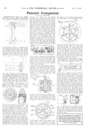
ELECTRICAL DRIVING GEAR.Johnson—No. 28,5116, dated 27th December, 1907.—This invention relates to electrical driving gear especially intended for motor road vehicles. The source of energy (M) drives, by means of bevel wheels VI , r2), a field magnet (Ed). The
rotation of the field magnet generates induction currents in the sets of coils (Ad!, A d al which are independent of each other. This generation of current exerts a torque of the same direction as that
of the magnetic field on the sets of coils (Adz, Adz). Two further coils (Em;, E m 2) carrying, respectively, sprocket wheels (cc, s, which are used to drive
the wheels of the vehicle independently of each other, are mechanically con fleeted to the two coils (Adz, Adz). As both sets of coils (Erni, Adz, and Ems, Ads) have exactly the same torque, the torques exerted on the driving wheels of the vehicle through the sprocket wheels (sr, 84 are likewise equal, but, as both systems of coils are only connected together through the magnetic fields, differences iii the number of revolutions of the sprocket wheels can take place when the vehicle is rounding curves.
DESTINATION INDICATOR.—Hart.
— No. 22,334, dated 11th December, 1907.
— The indicator comprises a box (a) divided by a partition (m) in which a
glass window (na) is arranged. Two rollers (b, c) are carried by a frame (e) so as to be easily removable, The rollers carry the screen (f) on which the name of the vehicle's destination is printed. The roller (8) is provided with a spring whilst the spindle of the roller .(c) is carried beyond the outer casing, or box (a), and a hand wheel (i) is mounted thereon. Also mounted on the spindle of the roller (c) is a toothed wheel (4) which is engaged by a pawl (/). The screen (f) is wound on to the lower roller (c) against the action of the spring on the upper roller (6), and is prevented from flying back by the pawl (1) and toothed wheel (4). A window (¢1) is provided in the front of the box (a) so that the destination on the screen (f) may be visible. A lamp (e) is provided in the interior (a) . of the box (a) so that the screen may be visible at night.