


Refinements in Power assisted Steering Gear
Page 48
If you've noticed an error in this article please click here to report it so we can fix it.
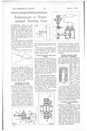
PAA STEERING system for large vehicles, where the driver's effort is amplified by the application of compressed air, is outlined in patent No. 591,545, by Bendix-Westinghouse Automotive Air Brake Co., Elyria, Ohio, U.S.A. With such a system there is a tendency for an oscillation to be pet up when running straight ahead, and the ' aim of the present scheme is to eli minate this.
The outfit consists of an air-operated cylinder (I) which works the drop-arm (2) of the steering. When the driver turns the steering wheel, a rod (3) is moved; this controls a slide valve (4) which admits air to one or other side of the piston.
To eliminate the possibility of oscilla
lion in the straight position, it is arranged to reduce the air pressure in the mid-position. This is performed by a two-lob:4J cam (5) which abuts the adjuster rod of a constant-pressure valve. In the position as shown, the air pressure is retained at a low pressure. As soon as the driver steers, however, the cam acts to increase the pressure, so that the power piston can make the necessary effort.
IMPROVED TRACTOR TRANSMISSION LAYOUT
PATENT No. 591,291, from Timken Detroit Axle Co., Detroit Michigan, U.S.A., covers the layout of a tractor transmission, with advantages of ease of assembly and efficiency in action.
The drawing is of a section of the tractor from the clutch to the final drive. The first unit is a power take-off (1); this is bevel driven from the main input shaft of the gearbox. Then follows a normal gearbox, the output shaft of which emerges at a low level. where it carries a bevel pinion (2). The bevel drives in the normal way a high-speed differential gear (3), the two shafts of which ing to side. extend outwards through the cascarry brake drums, one on each A final reduction is provided by a pair of spur gears (4) meshing with pinions on the differential. The casing is divided into three sections, united by bolting at points 5 and 6.
A STONE REMOVER FOR TWIN TYRES
AN attachment for ejecting stones as they are picked up by twin tyres forms the subject of patent No. 591,171, from G. White and A. Watson, 56, Lynwood Avenue. Marsh Mills, Plympton. Devon. The.clevice consists of a curved blade (1) formed with a fish-tail end which proje-ts into the space between the tyres and obstructs the orbit in which the stones move. The blade is clamped by the bolts holding the. leafspring (2) on to the axle tube.
TOOL FOR SPREADING TYRES
riNE of the most awkward jobs in the repair shop is to open the beads of an outer cover to enable inspection and repairs to the interior to be performed, and a tool for facilitating this operation is described in-patent No. 591,844 from E. Sturn, A. Emmett, and Woodhouse and Mitchell, Ltd., Clifton Bridge Works, Brighouse, Yorks.
,The tool consists of a pair of tong-like arms fitted with shaped ends (1) to
receive the beads of the tyre. A ratchettoothed arc (2), in conjunction with a spring-loaded pawl, maintains the position rather like a hand-brake lever. The tool is simply inserted between the beads' and the levers are then pulled apart until the desired width of opening is attained.
RUBBER BUSHING WITH IMPROVED FLEXIBILITY
AN inner sleeve, a rubber filling, and an outer sleeve form the basis of many rubber-mounted joints, and, whilst they are satisfactory in many ways, they are inclined to be more• resistant to radial than to
axial loading. To enable a unit to be made with any desired ratio between these two loadings is the object of a scheme shown in patent No. 591,730, by Dunlop Rubber C o., L t d., L Albany Street, N.W.1, T. Gray and W. Gurney.
The drawing shows a pictorial section of the proposed unit, and Illustrates the novel method of joining the inner and outer sleeves. They are connected by sloping " spokes " of bonded-on rubber, which can be varied in size and number to give any desired degree of resilience, in both axial and radial directions. The layout of the rubber pieces is such that they can be moulded in position and the mould extracted without damage.
A FLEXIBLE TRANSMISSION -JOINT
PATENT No 591,146, from T. Gray and the Dunlop Rubber Co., Ltd., 1, Albany Street, London, N.W.1, -discloses a flexible joint for uniting 'shafts which may be slightly out of line.
Referring to the drawing, a pair of metal pressings (1) forms the main easing and houses four flexible units, consisting of outer shells (2) and inner sleeves (3) bonded together by doubleconed rubber members (4). The inner sleeve receives a bolt from the shaft flange, whilst the outer part is held by the casing The drawing shims a section of one side of the joint.