


Plurality of Hard Inserts for Piston-ring Grooves
Page 28
If you've noticed an error in this article please click here to report it so we can fix it.
T"problem of providing a hardwearing ring groove in a soft piston is often complicated by the differing expansion rates of steel and light alloy leading to ultimate loosening of an.y cast-in parts. To overcome this trouble is the object of an improved insert shown in patent No. 540,990 by the Automotive Engineering Co„ Ltd., and others, 104, The
Green, Twickenham.
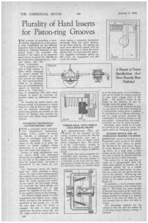
It is proposed to employ a large number of .sheet metal stampipgs (1) spaced around the periphery of the piston and secured by casting in. The inserts are about
0.032 in. in thickness, and are circumferentially spaced at intervals of about I in. Their large . area, in comparison with their small volume, is stated to overcome all troubles caused by differential expansion.
For locating the inserts before and during casting, it is proposed to attach them to a. ring of wire or strip which can be removed afterwards. The piston-ring grooves are formed in the inserts by turning, after casting, the hard and soft metals being machined together.
• AUTOMATIC CENTRIFUGAL CLUTCH-CONTROL UNIT CROM a renowned clutch specialist,
h e Borg-Warner Corporation, Chicago, U.S.A., comes, in patent No. 540,924, a refinement in the design of centrifugal units for automatically operating clutches. The object of the design is to allow the clutch to remain engaged during deceleration to a much lower speed . than that which will engage it.
Instead of being incorporated with the clutch itself, the centrifugal mechanism is a septa-ate unit, mounted on the side of the engine and driven from the dynamo shaft. Its action is transmitted to the clutch by rodwork.
Our illustration ' shows the centrifugal unit, which embodies a notary carrier (4) upon which spring-opposed. bob-weights (2) are pivotally mounted, Their motion exerts end-pressure on a slider (3) which operates the clutch. At low -speeds, the bob-weight springs (1) overcome the ellitch-springs and cause disengagement, but at high speeds the opposite is the case. This is the position shown in the drawing.
The different engine speeds at which engagement and release occur, respectively, are due to the geometry of the mounting of the springs (1).
be seen that when the Clutch is engaged, the axis of these springs. approaches the pivot centres (5), and the toggle action so created gives the AlS clutch spring a temporary mechanical advantage while the speed declines. In the other position, the springs are much more effectively placed, and the operating speed, up to which the clutch remains free, is proportionately higher. The suggested crankshaft speeds are 600 r.p.m. for engagement and 400 r.p.m. for release.
TIMBER. DRAG WITH SIMPLE _ AXLE ROCKING MEANS
AN adjustable-length traaller, pribiarily for the transport of tree trunks, is shown in patent No. 540,703 by Midland Vehicles, Ltd., and J. Parker Garner, both of Upper Grove Street, Leamington Spa. The vehicle is of the "pole-wagon " variety, in which the frame consists of a single girder, adjustable in respect of effective length.
This girder (2); which comprises two wood-filled steel channels, is permanently attached in the usual manner to a turntable at the front end for steering purposes, whilst the rear axle, with its associated frame, is slidably fitted
on to the main. girder, as is customary, and can be locked in various positions by pins which engage holes in ' the
girder. The patent is based on the design of the brackets (3 and 4) through which the girder slides.
These are pivotally mounted on pins (1), as, shown in the detail drawing of a ctoss-section, which gives a measure of articulation in a sideways direction, and on rough ground prevents the transmission of twisting stresses to the main girder. Alternatively, the bracket swivel-pin (1) can be above the pole. Obviously, there would be no need for swivels if the pole were round, but square poles are commonly preferred.
SEALING DEVICE FOR AN HYDRAULIC MASTER CYLINDER iMPROVED control of the fluid in an 1, hydraulic brake system is the object Of an outlet valve shown in patent No. 541.016-by B. Dick and J. I3ea.rd, St. Louis, Missouri, U.S.A. The drawing shows, on a large scale, a halfsection of the end of the master, cylinder, and it should be realized that the space on the left is filled with fluid. The outlet (1) to the pipe-lines is closed by a` spring-loaded valve (2) which seats against an annular rib of triangular section (3) on a rubber washer, which is itself sealed, by pressure on a wider rib (4) against the end wall of the cylinder. Pressure f9r this purpose is provided by the main return spring of the piston pressing on the 'flange (5).
In operation, a rise in pressure opens valve 2 and permits a flow of fluid into pipe 1. No return can occur because of the one-way action a the valve (2). When: the piston is-released, however, spring pressure on flange 5 is reduced and rim 4 can then be lifted by the line pressure and so allow the fluid to return.
The advantage claimed b for the scheme is that the lines are sealed off at-all times except during a change r)f pressure.