


DIFFERENTIALS THAI ECLUDE WHEEL-SPIN
Page 22
Page 23
If you've noticed an error in this article please click here to report it so we can fix it.
Two Inge Mechanisms Torque Eq Wheels in stances, bu Case, the 1 Gripping Other is ( and, in t Useful
nal-drive Distribute the Road Circumin One ',tier to the Vhen the y Ground
• Case, a L of It
FOR decades automobileengineers have been seeking a simple and practicabla means for overcoming the well
known trouble of the differential gear—as commonly used—namely, that all drive is lost when one wheel fails to grip. Now, almost simultaneously, come reports of two mechanisms devised wholly or partly for this purpose. No doubt the concentration of designers at the present time on chassis for cross-country work has stimulated efforts to solve this particular problem, but it is-still something of a coincidence that two schefnes should appear practically together. .
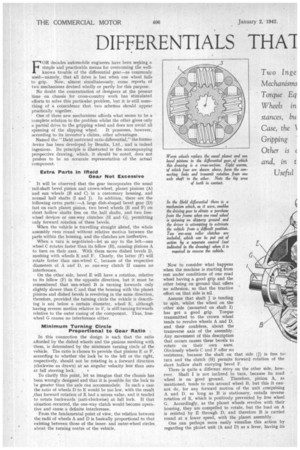
One of these new mechanisms affords what seems to be a complete solution to the problem whilst the other gives only a partial drive to the gripping wheel and does not avoid all spinning of the slipping wheel. It possesses, however, according to its inventor's claims, other advantages Named the "Held restricted ratio differential," the former device has been developed by Bendix, Ltd., and is indeed ingenious. Its principle is illustrated in the accompanying perspective drawing, which, it should be noted, does not profess to be an accurate representation of the actual component.
Extra Parts in Meld Gear Not Excessive
s It will be observed that the gear incorporates the usual tail-shaft bevel pinion and crown-wheel, planet pinions (A) and sun wheels (B and C) in a customary housing, and normal half shafts (I and J). In addition, there are the following extra parts :—A large dish-shaped bevel gear (D) fast on each planet pinion, two bevel wheels (E and F) on short hollow shafts free on the half shafts, and two freewheel devices or one-way clutches (H and G), permitting only forward rotation of these bevels.
When the vehicle is travelling straight ahead, the whole assembly runs round without relative motion between the parts within the housing, and the -clutches are ineffective. When a turn is negotiated—let us say to the left—sun wheel C rotates faster than its fellow (B), causing pinions A to turn on their axes. With them move dished bevels D, meshing with wheels E and F. Clearly, the latter (IT) will rotate faster than sun-wheel C, because of the respective diameters of A and' D, so one-way clutch H causes no interference.
• On the other side, bevel E will have a rotation, relative to its fellow (F) in the opposite direction, but it must be remembered that sun-wheel B is turning forwards only slightly slower than C and that the housing with the planet pinions and dished bevels is revolving in the same direction, therefore, provided the turning circle the vehicle is describing is not below a certain diameter, wheel E, although having reverse motion relative to F, is still turning forwards relative to the outer casing of the component. Thus, freewheel G causes no interference either.
Minimum Turning Circle
Proportional to Gear Ratio
In this connection the design is such that the ratio afforded by the dished wheels and the pinions meshing with them, is determined by the minimum turning circle of the vehicle. The ratio is chosen to provide that pinions E or F, according to whether the lock be to the left or the right, respectively, should not be rotating in a forward direction (clockwise as drawn) at an angular velocity less than zero at full steering lock, . 0 To clarify this point, let us imagine that the chassis has been wrongly designed and that it is possible for the lock to be greater than the axle can accommodate. In such a case the ratio of wheels D to E would be too low, with the result ,that forward rotation of E had a minus value, and it tended to rotate backwards (anti-clockwise) at full lock. If that situation occurred, the one-way clutch would become operative and cause a definite interferenoe.
From the fundamental point of view, the relation between the radii of wheels A and D is basically proportional to that existing between those of the innerand outer-wheel circles about the turning centre of the vehicle. Now to consider what happens when the machine is starting from rest under conditions of one road wheel having a good grip and the other being on •ground that offers no adhesion, so that the tractive effort on that side is nil.
Assume that shaft j is tending to spin, whilst the wheel on the other side (mounted on shaft I) has got a good grip, Torque transmitted to the crown wheel tends to revolve wheels A and D, and their confreres, about the transverse axis of the assembly. Any movement of this description that occurs causes these bevels to rotate on their own axes. Obviously wheels C and F offer no resistance, because the shaft on that side (j) is free to turn and the clutch (H) permits forward rotation of the short hollow shaft carrying bevel F.
There is quite a different story on the other side, however. Shaft I is not inclined to turn, because its road wheel is on good ground. Therefore, pinion A, as mentioned, tends to run around wheel B, but this it cannot do, for any forward motion of the unit comprising A and D, so long as B is stationary, entails reverse rotation of E, which is positively prevented by free wheel G. Accordingly, as the planet wheels revolve with their housing, they are compelled to rotate, but the load on A is resisted by E through D, and therefore B is carried round at a lower speed, with the planet assembly. One can perhaps more easily visualize this action by regarding the planet unit (A and D) as a lever, having its fulcrum at one end, where it bears against pinion E, having
force applied to it (forwards) at its other end, which coincides• with the axis of bevel A, and imparting movement at an intermediate point, where it engages with the circumference of wheel B.
To extend , this analogy, one may alternatively picture the lever as fulcrummed at the centre of the vehicle's turning circle, and as engaging with the tops of. the two driving wheels, then, whichever Wheel is tending to spin, forward motion is transmitted from it by the lever to the other wheel. The action is the same whether the vehicle is turning or going straight. Clearly the clutches • (G and H) prevent reversing the vehicle, so a control is required to put them out of action when it is required to run backwards.
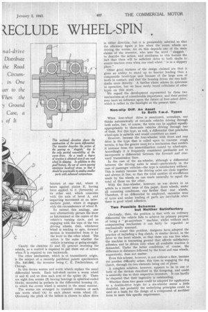
The other mechanism, which is of transatlantic origin, is the subject of a -recently published patent specification (No. 540,686), the inventor being C. E. Frederickson, of Chicago.
In this device worms and worm wheels replace the usual differential bevels. Each half-shaft carries a worm wheel (4 and 6) and so does each arm of the spider (5). There are eight free worms (3) having bearings in spherical-ended blocks, mounted in pockets in the differential housing (I), to which the crown wheel is secured in the usual manner.
The worms are arranged to transmit rotation of each sun worm wheel '(4) to each planet worm wheel (2). Obviously the pitch of the helices is chosen to allow drive
in either direction, hut it is presumably selected so that the efficiency figure is low when the worm wheels are driving the worms, for on this depends one of the main claims of the inventor, who uses the word " sluggish " to describe the action, and attributes to this feature the fact that there will be sufficient drive to both shafts to ensure traction even when one road wheel " is in a slippery place."
Other good features of the design claimed are that it gives an ability to stand up to heavier loading than a comparable bevel-type unit because of the large area of teeth in contact, and that the housing drives the two halfshafts more directly. A further claim relates to quietness in operation, but we have rarely heard criticisms of other types on this score.
We regard the development represented by these two mechanisms as of considerable importance, and their arrival may have an influence upon the future of four-wheel drive, which is rather in the limelight at the present time,
Non-slip Duff. An Asset to Both f.w.d. Types
When four-wheel drive is mentioned, nowadays, one thinks automatically of two-axle vehicles driving through both axles, but, of course, the term can be applied equally appropriately to three-axle vehicles driving through two of them. For this type, as well, a differential that precludes wheel-spin is suitable and would constitute an asset.
However, because the four-wheeler with front and rear drive is the type that is called upon to traverse rough terrain, it has the greater need,for a mechanism that renders it immune from the immobilization caused by wheel-spin. Accordingly it is frequently considered preferable not to incorporate a differential between the fonvard and rearward transmission lines.
In the case of the six-wheeler, although a differential between the driving axles is usual—particularly in the case of passenger vehicles—the type is satisfactory without. This is mainly because the driving axles are close together and always in line, so that the total number of revolttions made by the wheels on one tends naturally to equal the total of those on the other.
With the four-wheeler, however, as was shown in an article in a recent issue of this paper, front wheels, under all cornering conditions, run farther than rear wheels, Therefore, if no differential be employed, excessive wear of tyres and undue loading, of parts are inevitable when there is good wheel adhesion.
Two Possible Schemes but Neither Satisfactory
Obviously, then, the position is that with an ordinary differential the vehicle fails to achieve its primary purpose of being a " go-anywhere "machine, whilst without such compensating mechanism it can fairly be regarded as mechanically unsound. To get round this problem, designers have._ adopted the practice of including a dog clutch, or similar device, in the drive to the front wheels, so that these can run free when the machine is traversing ground that affords satisfactory adhesion and be driven only when all available traction is demanded. Under the latter conditions, of course, the difference in distances followed by the front and rear wheels, respectively, does not matter.
Even this scheme, however, is not without a flaw, because Yet another difficulty arises, this time in engaging the dog clutch, through its two elements being out of phase.
A complete solution, however, appears to lie in one or both of the devices described in the foregoing, and credit is assuredly due to their respective inventors. It can hardly be'disputed that their ingenuity is outstanding.
Whether these two gears could be adapted for application to a double-drive bogie for a six-wheeler seems a little doubtful, but probably the underlying principles could be used as a basis for the design of a component of modified form to meet this specific requirement.