


PATENTS SUMMARIZED.
Page 22
If you've noticed an error in this article please click here to report it so we can fix it.
A New Gas Equipment.
A gas-fuel-supply apparatus, which is interesting both as a whole and in regard to its details, is the sublect of a patent by P. Lamplough. the number of the specification being No. 120,424. In application it is claimed Unit it is useful in connection with any gas which is suitable for internal-combustion engines, although, apparently,it was in the first case devised with a view to utilizing a waste product resulting from the conversion of heavy oils into lighter oils by
hr nging the former into contact with bet nickel. This particular gas is easily liquefied under pressure, and in this form is readily admitted to the container. There appears to be no reason, however, why this apparatus.should not, with very slight modification, be suitable for coalgas.
The equipment as described is complete from the reservoir for the compressed gas to the throttle valve of the carburetter, and it contains many features of novelty. Altogether it consists of the following: high-pressure containei with inlet and outlet valves, reducing valve, pipe to lowpressure container, inlet valve to the latter controlled by means of a diaphragm so that excessive pressure within this second container is•impossible, pipe from the low-pressure receiver and the carburetter, even the !at-named .lomponent bein&I also described in detail.
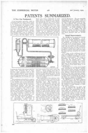
Not the least feature of interest is that concerning the construction of the high-preseure holder : this is cylindrical, with domed ends, the cylin
drical part being con;tructed of steel plate which is corrugated, the corrugations taking the form of a screw thread. The domed ends are also of steel plate, and have cylindrical extensions corrugated in a similar manner to the main body of the container, and these ends screw into the body, the edges of the metal of the cylinder being subsequently hammered over on to the domed ends and welded. As an additional safeguard, cast-iron plates formed to fit the ends of the receiver are also provided for in the construction and they are-secured by long bolts passing from end to end of the receiver. These castings serve also to receive the nipples to which may be connected the inlet and outlet valve. Round the corrugations of the cylinder is wound wire under high tension as an additional source of strength.
The construction of the reducing valve will he gathered from a reference to the drawing which we reproduce; it is of the diaphragm type. The secondary receiver is a plain cylinder, with one end —that on the left in our drawing—prepared for the reception of the inlet and outlet branches. The other end is convex to the exterior, and clamped between cover and flange of the receiver is a diaphragm of some flexible material which is subject to the pressure of the ga,s within the container. A, long rod from this diaphragm couples to the inlet valve, so that when the pressure within this receiver exceeds a certain amount the valve closes. The carburetter is quite a simple affair, and its construction can almost be gathered from the diagrams without any need for description.. The gas. enterathe innermost )of three cylinders' which is closed enthe top, but is perforated as to its walls a short distance from the top. Air enters between the outermost.; and middle cylinders, the middle one being perforated in a similar manner to the Innermost. Air enters inwardly in the perforations in the middle tube and meets gas passing out throug11 he perforations in the central tube. These mix and travel upwards pass the throttle valve.
Detail Improvements.
No. 120,402 is a two-Speed andreverse gearbox by H. P. Saunderson. It ap pears to be suitable mainly for agricul tural tractors. Separate. levers working on quadrants are provided, one ?for re verse and one for forward motion. Each is secured in its operative position in the usual way ha notches on'. the quadrant. A guard in the form of a bar, pivoted at its centre is positioned so that it is impossible to operate either gear liner until the other has been moved to the neutral position. S. E. Alley, of the well-known firm of and MacLellan, in No. 120,466, describes a modified arrangement of valve gear for a steam-engine. The engine is horizontal ; the inlet valves are placed above mid the exhaust below. The timing gears are contained in a narrow casing, readily accessible. The crankshaft may be slid longitudinally so as to effect control of the steam supply, or as a reverse gear.
The Daimler Co.'s patent change-speed gear, describedin No 120,481, partiati larly concerns heavy vehicles, and. especially those in which the gearbox is placed some distance behind the driver's seat.
Instead of the usual transverse changespeed shaft and projecting selector bars,
a rocker shaft is carried by the side of the frame as a means of communication from change:speed lever to gearbox.
No. 120,5/0, by C. H. Ingall, refers to an ingenious hollow valve, the in.torior of which is placed into communication with the atmosphere each time it lifts, through the medium of small shifting or automatic poppet valves. In the arrangement of motor and plough described in No. 120,586, by R. E. R. James, the ploughshares are car ried within the wheelbase, the driving wheel travels in the furrow last cut, and the particular feature of this invention
appears to be that the ploughs are free, within limits, to move either vertically or laterally independently of the tractor. The Dunlop Rubber Co. describe in No. 120,589 several arrangements of multi-solid band tyres.