


Patents Completed.
Page 22
If you've noticed an error in this article please click here to report it so we can fix it.
Complete specifications of the following patents will be sent to any address in the United Kingdom by the Sale Branch, Patent Office, Holborn, W.C. upon receipt of eightpence per copy.
Resilient Solid Tires.
L. Brown, and Charles Macintosh and 'Co., Ltd., No. 7751, dated 30th March, 1912.—It is found that when solid rub'ber tires are mounted in steel rims the hammering effect of the rigid rim causes the tire to dateriorate, and the rigidity of the rim also decreases the resilience of the tire to some extent. These difficulties are overcome according to the present invention, by velcanizmg to the inner face or base of the tire a hard, slightly resilient strip of material such as hard rubber, balata, or other similar substance, mixed with some fibrous material preferably of a textile character. Various sections of tire are described and illustrated. For example, the joining surface may be plain or undercut in circumferential or transverse grooves to enable the rubber to grip the fibrous base. It is also proposed to insert a sheet of vulcanite between these two, or to embed sheets of canvas in the fibrous base,
Front-wheel Springing.
The Weiseley Tool and Motor Car Co., Ltd., A. A. Remington and A. J. Rowledge, No. 25,421, dated 15th November, 1911.—There are described in this specification several methods of mounting the -front wheels of a motor vehicle ; the common feature of them all consists in the provision of two stub-axles for the front wheels, and an invited elliptic spring situated across the front of the van. The stub axles are each carried on a parallel link work, so that the wheels can yield vertically independently of one another. Vertical movement is transmitted to the frame through the spring, and is re
duced in extent. In some cases, one of the horizontal suspension links may be removed, and its place taken by the elliptic spring. In another construction a helical spring is interposed between the frame and the elliptic spring; in this last case the transverse elliptic spring may have substituted for it a rigid bar, all the necessary resilience being provided by the helical spring.
Lubricating the Engine,
W. McCurd, No. 2539, dated 31st January, 1912.—There are two sumps in this engine, into one of which the connecting rods dip to take off the proper quantity of oil necessary according to the dip system. Properly speaking, the invention gives an arrangement for always keeping the oil in the dip sump at a constant level. This is done by means of a long tube which passes right along the sump and which has holes in it, so that the oil can run into the interior of the tube. The latter is mounted in bear ings which also have holes corresponding to two of those in the tube, and connected to the main sump in the bottom of the crankcase. There is a cam-gear for working the tube back and forth, so that the dip sump is connected to the main sump at predetermined intervals. Thus the level of the oil is maintained and the efficiency of the lubrication system improved.
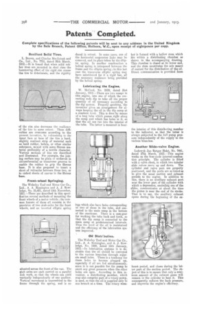
Oil Distebution.
The Wolseley Tool and Motor Car Co., Ltd., A. A. Remington, and A. J. Rowledge, No. 1099, dated 15th January, 1912.—in lubrication systems it is desirable that the oil should be conveyed to the various branches through separate small holes. There is a tendency for these holes to become plugged up, especially if all are fed simultaneously, since it is not possible for the pump to exert any great pressure when the other holes are open. According to this invention, a distributing member, which may also comprise part of a rotary pump, is used, so that the oil is supplied only to one branch at. a time. The rotary mem
ber is formed with a hollow stem which fits within a distributing chamber as shown in the accompanying drawing. This chamber is closed at its lower end, and the stem constitutes the sole means of control for the distribution of the oil. Direct. communication is provided from the interior of this distributing member to the indicator, so that the latter is always subjected to the full pump pressure independently of the supply to the various branches.
Another Slide-valve Engine.
Lodewvk Jan Rutger Hoist, No. 7441, dated 27th March, 1912.—Thia engine works on the four-cycle internal-combustion principle. The cylinder is fitted with a valve chest, in which two tubular slide valves move up and down. The cylinder and valve port are properly positioned, and the ports are so timed as to give the usual suction and exhaust periods to the engine. In addition to this, there is an auxiliary exhaust port near the lower part of the cylinder with which a depression, encircling one of the slides, communicates at about the time the piston is near the end of its stroke. That is to say, the auxiliary exhaust opens during the beginning of the ex
period, and closes during the latter part of the suction period. The object of this is to ensure that only a minimum amount of the exhaust gases will remain in the cylinder to heat it. This consequently reduces the back pressure, and improves the engine's efficiency. haust