


A Single-plunger Injection Pump
Page 64
If you've noticed an error in this article please click here to report it so we can fix it.
DATENT No. 647,687, which comes
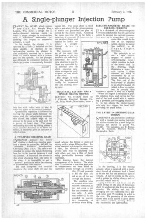
from C.A.V., Ltd., Warple Way,* London, W.3, shows a design for a multi-cylindered injection pump in which a single plunger, in conjunction with a distributor mechanism for diverting the output to successive cylinders, is used.
In this .design, the plunger (I) is operated. by a cam (I) tneunled on the main spindle. • In addition to its reciprocating motion, the plunger is also uniformly revolved by a crownwheel (3) which meshes with a helical gear on the.. spindle.. As the plunger goes through its composite motion, its discharge groove is successively brought
into line with radial ports (4 and 5) which are piped to the various cylinders.
Quantitative regulation is achieved by varying the phase angle between the rotary and the reciprocating motions; this allows the control edge of the plunger to be open to the spill part for a greater or lesser time. The phase relationship is varied by sliding pinion 6 in an endwise direction; as its teeth are helical. it therefore gives an advance or retard action_ A TWO-SPEED STEERING GEAR
DESIGNED specially for heavy vehicles, a dual-ratio Steering gearbox is shown in patent No. 647,405, by Thompson Products Incorporated, Cleveland, Ohio, U.S.A. The unit is not intended to replace the standard steering box, but to be inserted between it and the column. A feature of the scheme is that when changing from one ratio to the other, it is impossible to get a " neutral " position in which the steering is disconnected from control.
The unit comprises two co-axial members. the input shaft (I) and the output (2). The input shaft is fitted with a sun-wheel (3) the planet-pinions of which are journalled on pins (4) carried by the output shaft. Assuming the outer gear-ring (5) to be held, a reduction is obtained; if, however, the two members (input and output) be locked to
gether, a straightthrough drive is
created. • The necessary holding of the outer ring and Locking of the two members are selectively performed by . multiplate clutches 16 and 7). These are controlled by an external lever (8) which operates " earnplates arranged to apply pressure to one clutch or the other.
The design is such that the gearbox can readily be introduced into any existing steering gear.
MULTI-CELL BATTERY HAS A SINGLE FILLING ORIFICE DATENT No. 647,630, from the 1 Chloride Electrical StorageCo., Ltd., Exide Works, Manchester, shows a novel scheme for fitting a multi-cell battery with a single filling orifice. The prime essential in a design of this nature is that, for electrical reasons, the several cells must be insulated from each other, not even a film of liquid being permissible between adjacent electrodes.
The drawing shows the internal arrangement of the battery. The single filler (1) is located at one end, and when its compartment has been filled the electrolyte passes through an overflow tube (2) and proceeds to fill the next cell, and so on, all the way through the battery.
The overflow tubes are treated with a nonwettable substance, so that not even a wet film can connect adjacent cells. A single vent orifice (3) is also provided to prevent t he formation o air-locks when filling. ELECTRO-MAGNETIC BRAKE TO USE LESS CURRENT
IT is a drawback of electro-magnetic 1 brakes and clutches that if a powerful action be desired, the current consumption goes up in proportion_ To overcome this trouble is the aim of an improved action, shown in patent No, 647,832, by G. Du,y ck, Tangier, Morocco. ,
The principle is to use • a light electromagnet to . control a self-energizing •unit which provides the hulk of the power used.. In the drawing, which illustrates a brake, the axle carries a drum member (I) which is surrounded by an external band-brake (2). The .free_ end, of the brake-band is attached to an electro-magnet (3) which is free to revolve.
but is , usually held stationary against a stop by a spring.
When the magnet is energized it grips the rotating drum, and carries the free end of the band round with it. imparting a powerful self-wrapping motion to it. In this scheme the electromagnet acts only as a trigger, the band itself providing the main force...
THE LATEST IN STEERING-GEAR DESIGN.'
STRENGTH and. durability combined with a considerable saving in weight are virtues claimed for a new design of steering box shown in patent No. 646,601. The patentees are R. Bishop and R. Johnston, Flowton Priory, Harpenden, Herts.
In the drawing, 1 is the steering column which is screwed with a multistart thread, of whatever lead is found to be the best for the particular type of vehicle. A nut (2) works on the screw, and is guided by sliding along a pair of parallel rods (3 and 4).
Lying behind the nut is an arm (5) which swings on the axis of the output shaft (6) and carries the drop-arm on its exterior. The sliding nut and the swinging arm are connected by a pinand-roller joint (7) working in a slot in the arm. The geometry of the scheme shows that a fast action is given about the central position, slowing down as the extremities are approached.