


A NEW FORM OF FLUID BRAKE.
Page 30
If you've noticed an error in this article please click here to report it so we can fix it.
A Résumé of Recently Published Patent Specifications.
JC. BECK, of Seattle, U.S.A., in specification No. 244,961, . describes an improvement in that class of hydraulic brakes in which the fluid itself provides the friction which causes the retarding effect by being forced through a contracted aperture. Experiments in this direction in connection with brakes have been tried from time to time, but no very serious effort seems to have been made.
It is rather curious that this very promising form of brake should not have attracted the attention of experimenters more, considering the promise the plan offers, and in order to encourage further efforts in this direction we publish a special article on the subject of hydraulic brakes and clutches on page 835 of this issue. In the present instance the inventor points out that his brake is noiseless in its operation and that it overcomes all the objections common to friction brakes.
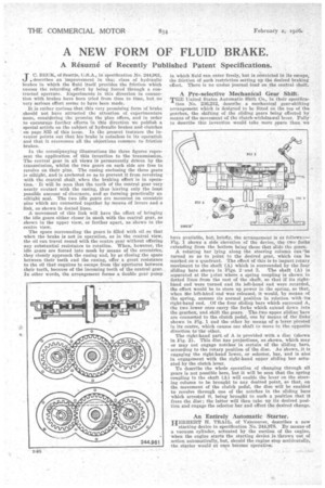
In the accompanying illustrations the three figures represent the applicatien of this invention to the transmission. The central gear in all views is permanently driven by the transmission, whilst the two gears on each side are free to revolve on their pins. The casing enclosing the three gears is oiltight, and is anchored so as to prevent it from revolving with the central shaft when the braking effect is in operation. It will be seen that the teeth of the central gear very nearly contact with the casing, thus leaving only the lea,st possible amount of clearance, and so farming practically an oiltight seal. The two idle gears are mounted on eccentric pins which are connected together by means of levers and a link, as shown in dotted lines.
A movement of this link will have the effect of bringing the idle gears either closer in Mesh with the central gear, as shown in the upper view, or farther apart, as shown in the centre view.
The space surrounding the gears is filled with oil se that when the brake is not in operation, as in the central view, the oil can travel round with the centre gear without offering any substantial resistance to rotatibn. When, however, the idle gears are forced into mesh by means of the eccentrics, they closely approach the casing and, by so closing the space between their teeth end the casing, offer a great resistance to the oil that requires to escape from the apertures between their teeth, because of the incoming teeth of the central gear. In other words, the arrangement forms a double gear pump
in 'which fluid can enter freely, but is restricted in its escape, the friction of such restriction setting up the desired braking effect. There is no undue journal lead on the central shaft.
A Pre-selective Mechanical Gear Shift.
TEE United States Automatic Shift Co., in their specifica tion No. 236,212, describe a mechanical gear-shifting arrangement which is designed to be fitted on the top of the gearbox, the shifting of the sliding gears being effected by means of the movement of the clutch-withdrawal lever. Fully to describe this invention would take more space than we have available, but, briefly, the arrangement is as follows :— Fig. i shows a side elevation of the device, the ttvo forks extending from the bottom being the that slide the gears.
A rotating bar lying along the steering column can 'be turned So as to point to the desired gear, which Can be marked, on a quadrant. The effect of this is to impart rotary. mot4ment to the shaft (A) which is surrounded by the four sliding bars shown in Pigs. 2 and 3. The shaft (A) is separated at the Fount where a spring coupling is shown in dotted lines from the rest of the shaft, so that if its righthand end were turned and its left-hand end were retarded, . the effect would be to store up power in the spring, so that, when the left-hand end was released, it would, by means of the spring, assume its normal position in relation with its right-hand end. Of the four sliding bars which surround A, the two lower ones carry the forks which extend down into the gearbox, and shift the gears. The two upper sliding "bars are connected to the clutch pedal, one IV means of the links• shown in Fig. 1 and the other bymeam of a leverpivoted' in its centre, which causes one shaft to move in the opposite
direction to the other. • ' The right-hand part of A is provided with a disc (shown in Fig, 2). This disc has projections, as shown, which may or may not engage notches in certain of the sliding bars, • according to the rotary position of the disc. As shown, it is engaging the right-hand lower, or selector, bar, and is also in engagement with the right-hand upper sliding bar actuated by the clutch lever.
To describe the whole operation of changing through all gears is not possible here, but it will be seen that the 'spring coupling in the shaft (A) will enable the lever on the steering column to be brought to any desired point, so that, on the movement of the clutch pedal, the disc will be enabled to revolve through one of the notches in the sliding bars which arrested it, being brought to such a position that it frees the disc; the latter will then take up its desired position and engage the selector bar and effect the desired change.
An Entirely Automatic Starter.
HERBERT H. TRAIL, of Vancouver, describes a new
starting device in specification No. 244,978. By MUMS of a vacuum cylinder, actuated by the suction of the engine, when the engine starts the starting device is thrown out of action automatically, but, should the engine stop aceidentally, the starter would at once become operative.