


FLUID BRAKES AND CLUTCHES.
Page 11
Page 12

If you've noticed an error in this article please click here to report it so we can fix it.
Although Extremely Little Use Has Been Made of Fluid Friction in Transmission and Braking, there is Ample Evidence that Further Investigation of Its Merits is Warranted.
IN our page which deals with recently published patents, we refer to patent No. 244,961, in which a new form of fluid brake is described. When we say " fluid brake," we do not mean a brake in which two frictional surfaces are brought into contact by means of hydraulic pressure, but where the action of forcing a 'fluid through a contracted aperture Produces the re' quired retarding effect. Experiments in the direction of designing brakes and clutches on these lines have• from time to time been carried out in a fitful way, but we are rather surprised that more energy has not been directed towards the production of a brake and a clutch which could operate for long periods without the wearing away of metal or fibrous material. We are aware that difficulties await the investigator in this direction, but had such difficulties deterred all hivestigations of a similar kind there would have been no motor industry. In all directions leading towards the design of a more perfect vehicle, there are lions in the path, which is, consequently, strewn with the whitening bones of pioneers, so the fact of there having been unsuccessful efforts in this direction need not be taken as a sign that the Mecca can be reached by no man.
To act as an encouragement to those who may be inclined to make experiments In the direction of such. brakes and clutches we give two extracts from an interesting book -entitled "Details of Typical Mechanisms," by C. M. Linley, published by Scott Greenwood, London.
A Simple Type of Hydraulic Clutch.
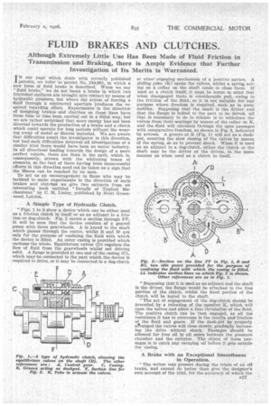
"Figs. 1 to 3 show a device which can be either used as a friction clutch in itself or as an adjunct to a friction or dog-clutch. Fig. 2 shows a section through FF. It will be seen that the device consists of a geared pump with three gearwheels. A is keyed to the shaft which passes through the centre, whilst B and 131 are only for the purpose of confining the fluid with which the device is filled. An outer casing is provided which encloses the whole. Equilibrium valves (D) regulate the flow of fluid from the gearwheels whilst not driving solid. A flange is provided at one end of the casing (C), which maybe connected to the part which the device is required to drive, or it may be connected to a dog-clutch or other \engaging mechanism of a positive nature. A sliding yoke (K) opens the valves, whilst a spring acting on a collar on the shaft tends to close them. If used as a clutch itself, it must be borne in mind that when disengaged there is considerable pull, owing to the friction of the fluid, so it is not suitable for any purpose where freedom is required, such as in automobiles. Supposing that the shaft is the driver and that the flange is bolted to the part to be driven, all that is necessary to do to release is to withdraw. the valves from their seatings by means of the collar on K, and the fluid will circulate through the open passages with comparative freedom, as shown in Fig. 3, indicated by arrows. A groove at E (Fig. I) will act as a dashpot, ensuring the slow closing of the valves by means of the spring, so as to prevent shock. When it is used as an adjunct to a dog-clutch, either the clutch or the shaft may be the driver or the driven, in the same manner as when used as a clutch in itself.
"Supposing that it is used as an adjunct and the shaft Is the driver, the flange would be attached to the free portion of the clutch, whilst the fixed portion of the clutch will be keyed to the shaft.
"The act of engagement of the dog-clutch should be preceded, by a releasing of the member K, which will open the valves and allow a free circulation of the fluid. The positive clutch can be then engaged, as all the resistance it has to overcome is the inertia and friction o the fluid and gears. If the dash-pot be' properly arranged the valves will close slowly, gradually increasing the drive without shock. Passages should be allowed for free oil in all cases between the pressure chamber and the exterior. The object of these passages is to catch any escaping oil before it gets outside the casing.
A Brake with an Exceptional Smoothness in Operation. •
"The writer was present during the trials of an oil brake, and cannot do better than give the designer's own account of the trial, for the accuracy of which the B27 writer can vouch. This appeared in the • Homeless Age,' July 1st, 1914 :— I cannot claim to have more than an experimental experience of this class of brake, but perhaps even this may be of interest. " The type on which the experiment was carried out was a 5-ton chain-driven lorry.
" A sprocket wheel was fixed on the differential
sleeve in the place usually occupied by the brake drum. An ordinary geared pump, such as used for oil or suds, was mounted on the chassis, and coupled up to the differential by means of a chain running at even speed. A dog-clutch for engaging and disengaging was provided. The suction and delivery pipes of the pump were both led to an open tank containing four gallons of oil. At the end of the delivery pipe a common tap was fixed, provided with a lever for regulation. When going downhill the first operation was to engage the dogclutch, and then to turn off the tap gradually. The result was marvellous.
" ' The vehicle came to a stop as if some outside force, such as a rope around a cleat, had gradually brought It to a standstill. Long hills were negotiated, and the vehicle kept at a walking pace without any inconvenient rise in the temperature of the oil. A learned professor worked out the volume of oil necessary to dissipate the heat generated as some 500 gallons. I thought he was a little out somewhere, so made a pot shot of four gallons, which seemed quite enough for the longest hill we could find, No precautions were taken to prevent leakages from the pump, and fine streams poured out from unseen apertures in all the joints and around the shafts. All that was done was to fit a hood over the pump so that all leakages went back to the tank. The experiment wan highly successful, and the device was only turned down on the grounds of cost.'
"Heenan and Fronde's' dynamometer is much on the lines of the experiment described above, but is, of course, for stationary purposes. For prolonged tests it has proved that the fluid brake is superior to all others, unless actual work such as generating electric current be done."