


Oil Cooling for Oil-Engine Pistons
Page 76
If you've noticed an error in this article please click here to report it so we can fix it.
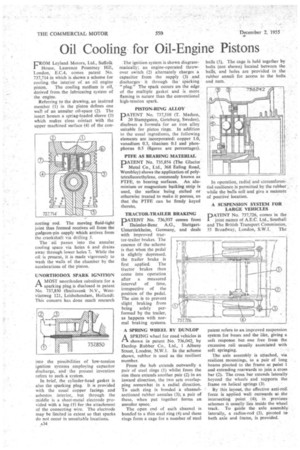
FROM Leyland Motors, Ltd., Suffolk House, Laurence Pountney Hill, London, E.C.4, comes patent No. 337,714 in which is shown a scheme for cooling .the interior of an oil engine
piston. The cooling medium is off, derived from the lubricating system of the engine.
Referring to the drawing, an inserted member (1) in the piston defines one wail of an annular oil-space (2). The insert houses a spring-loaded sleeve (3) which makes close ccintact with the upper machined surface (4) of the con fleeting rod. The moving fluid-tight joint thus formed receives oil from the gudgeon-pin supply which arrives from the crankshaft via drilling 5.
The oil passes into the annular_ cooling space via holes 6 and drains away through lower holes 7. While the oil is present, it is made vigorously to wash the walls of the chamber by the accelerations of the piston.
UNORTHODOX SPARK IGNITION
AMOST unorthodox substitute for a sparking plug is disclosed in patent No. 737,850 (Smitsvonk 'N.Y., Westvlietweg 121, Leidschendam, Holland). This concern has done much research
into the possibilities of /ow-tension ignition systems employing capacitor discharge, and the present invention refers to sucha system.
In brief, the cylinder-head gasket is also the sparking plug It is provided with the usual copper facings and asbestos interior, but through the middle is a sheet-metal electrode provided with a lug (1) for the attachment of the connecting wire. The electrode may be limited in extent so that sparks do not occur in unsuitable locations.
A34 The ignition system is shown diagrammatically; an engine-operated throwover switch (2) alternately charges a capacitor from the supply (3) and discharges it through the• sparking "plug." The spark occurs on the edge of the multiple gasket and is more flaming in nature than the conventional high-tension spark.
PISTON-RING ALLOY DATENT No. 737,510 (T. Madsen, • 24) Stampgaten, Goteburg, Sweden), discloses a formula for an iron alloy suitable for piston rings; In addition to the usual ingredients, the following elements are incorporated: copper 1.0, vanadium 0.3, titanium 0.1 and phosphorus 0.5 (figures are percentages).
PTFE AS BEARING MATERIAL
PATENT No. 735,854 (The Glacier Metal Co., Ltd., 368 Ealing Road, Wembley) shows the application of polytetraffuorethylene, commonly known as PTFE, to bearing surfaces. An aluminium or magnesium backing strip is used, the surface being etched or otherwise treated to make it porous, so that the PTFE can be firmly keyed thereto.
TRACTOR-TRAILER BRAKING
PATENT No. 736,937 comes from Daimler-Benz A.G., StuttgartUntertitrIcheim, Germany, and deals with improved tractor-trailer brakes. The essence Of the, scheme is that when the pedal is slightly depressed, the trailer brake is first applied. The tractor brakes then come into operation after a measured interval of time, irrespective of the position of the pedal. The aim is to prevent slight braking from being solely performed by the trailer, as happens with normal braking systems.
A SPRING WHEEL BY DUNLOP
ASPRING wheel for road vehicles is shown in patent No. 736,042, by Dunlop Rubber Co., Ltd., 1 Albany Street, London, N.W.1. In the scheme shown, rubber is used as the resilient member.
From the hub extends outwardly a pair of steel rings (1) whilst from the rim there extends another pair (2) in an inward direction, the two sets overlapping somewhat in a radial direction. To each ring is bonded a channelsectioned rubber annulus (3); a pair of these, when put together forms an annular space.
The open end of each channel is bonded to a thin steel ring (4) and these rings form a cage for a number of steel balls (5). The cage is held together by bolts (not shown) located between the balls, and holes are provided in the rubber annuli for access to the bolts and nuts.
In operation, radial and circumferential resilience is permitted by the rubber while the balls roll and give a measure of positive location.
A SUSPENSION SYSTEM FOR LARGE VEHICLES
PATENT No. 737,726, comes in the joint namei of A.E.C. Ltd., Southall and The British Transport Commission,
55 Broadway, London, S.W.1. The patent refers to an improved suspension system for buses and the like, giving a soft response but one free from the excessive roll usually associated with soft springing.
The axle assembly is attached, via resilient mountings, to a pair of long beams pivoted to the frame at point 1 and extending rearwards to join a cross bar (2). The cross bar extends laterally beyond the wheels and supports the frame on helical springs (3).
By this layout, the effective anti-roll force is applied well outwards at the intersecting point (4); in previous schemes it usually lies inside the wheel track. To guide the axle assembly laterally, a radius-rod (5), pivoted to both axle and frame, is provided.