


Patents Completed.
Page 18
If you've noticed an error in this article please click here to report it so we can fix it.
Complete specifications of the following patents will be sent to any address in the United Kingdom upon receipt of eightpence per copy at the Sale Branch, Patent Office, Holborn, W.C.
LIQUU)-FUEL VAPORIZER.—Wilson and Another.—No. 26,248, dated 4th December, 1908.—The object of the present invention is to enable benzol, coal tar, naphtha and the like to be vaporized so that it may be utilized for the generation of steam. This is effected first by imperfectly vaporizing the fuel, and then by introducing highly-superheated steam into such vapour. The mixture of mixing chamber where vaporization is completed, after which the mixture is passed through an induction tube, where vapour and steam is then passed into a it is mixed with air, and finally to the burner. The fuel-supply pipe is coiled once round the interior of the boiler and then passed down to the fire pan, where a superheated-steam pipe is connected thereto. At this point, the imperfectlyvaporized fuel is mixed with the highlysuperheated steam, and the mixture is conveyed through a coiled portion of the pipe arranged above a number of burners and finally to a nozzle, the nose of which is directed towards an induction pipe. The steam and vaporized fuel, passing into the induction pipe, are mixed with air, and the mixture passes from the induction tube to a number of burners which are disposed radially within the fire pan.
VALVES FOR INTERNAL-COMBUSTION ENGINES. — Sears.—No. 2,228, dated 29th January, 1909.—This invention relates to valves for combustion engines of the rotary cylindrical type, and it has for its object so to dispose the valves that distortion due to unequal expansion is reduced to a mini
mum, and also to increase the efficiency of the engine. A cylindrical water. jacketed valve-casing is disposed longitudinally along the heads of the working cylinders, and is provided with a number of ports communicating with the coin bastion chambers of the working cylin. ders. Concentrically mounted within tho water-jacketed casing is a second or inner cylindrical casing which communicates with the exhaust, and also hat; a number of ports communicating with the interior of the outer valve casing. Between the outer and inner cylindrical casings is an annular sleeve valve, which communicates with the induction pipe and has a number of ports which is adapted to register at the proper moment with the ports in the working cylinder heads, and also another set of ports which is adapted to establish communication between the cylinder heads and the exhaust ports provided in the inner cylindrical casing.
SPARKING PLUG. — Riley. — No. 16,328, dated let March, 1909.—This invention relates to sparking plugs of the type in which the sparking of the latter can be observed. The plug is screwed into a tubular member, which is in turn screwed into the cylinder wall. At a point in the tubular member diametrically opposite to the elec.
trades of the sparking plug, a hole is provided, which is covered by a piece of glass suitably bolted to the tubular member and provided with asbestos washers to render the joint gas-tight. The tubular member is also provided with an extension which screws into the latter, and this extension affords space for the compression of the explosive mixture past the electrodes of the plug so as to insure ignition.
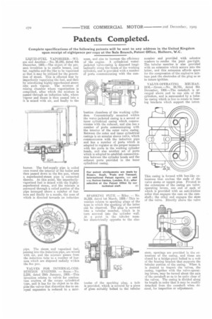
VALVE-OPERATING MECHANISM.—Green.—No. 26,731, dated 9th December, 1908.—The camshaft is arranged above and to one side of the cylinders, and is surrounded by a tubular casing which is free to rotate in bearing brackets which support the latter.
This casing is formed with box-like extensions that enclose the ends of the valve stems or tappet pins. Pivoted to the extensions of the casing are valveoperating levers, one end of each of which is provided with an anti-friction roller that engages the cam on the camshaft ; the other end engages the stem of the valve. Directly above the valve stem, openings are provided in the extensions of the casing, and these are closed by a bridge-piece bolted to a web of the bearing bracket that supports the tubular portion of the casing. When it is desired to inspect the valves, the casing, together with the valve-operating levers, may be turned about the axis of the camshaft so as to be quite clear of the valves. The casing is divided along its length in order that it may be readily detached from the camshaft when desired, for inspection or adjustment.