


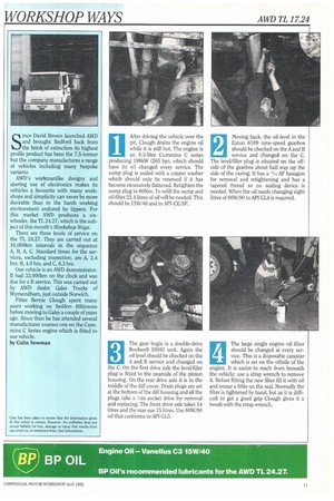
After driving the vehicle over the pit, Clough drains the
Page 99
Page 100
Page 101
Page 102
If you've noticed an error in this article please click here to report it so we can fix it.
engine oil while it is still hot. The engine is an 8.3-litre Cummins C series producing 198kW (265 hp), which should have its oil changed every service. The sump plug is sealed with a copper washer which should only be renewed if it has become excessively flattened. Retighten the sump plug to 80Nm. To refill the sump and oil filter 22.4 litres of oil will be needed. This should be 15W/40 and to API-CE/SF. Moving back, the oil level in the Eaton 6109 nine-speed gearbox should be checked on the A and B service and changed on the C. The level/filler plug is situated on the offside of the gearbox about half way up the side of the casing. It has a '°/ AF hexagon for removal and retightening and has a tapered thread so no sealing device is needed. When the oil needs changing eight litres of 80W/90 to API CIA is required.
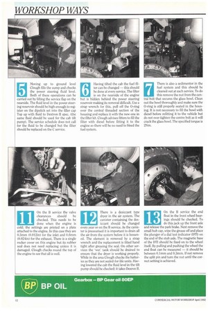
The gear bogie is a double-drive Rockwell SSHD unit. Again the oil level should be checked on the A and B service and changed on the C. On the first drive axle the level/filler plug is fitted to the nearside of the pinion housing. On the rear drive axle it is in the middle of the diff cover. Drain plugs are set at the bottom of the diff housing and all the plugs take a 'bin socket drive for removal and replacing. The front drive axle takes 14 litres and the rear use 15 litres. Use 80W/90 oil that conforms to API GL5.
3
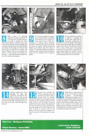
The large single engine oil filter should be changed at every service. This is a disposable canister which is set on the offside of the engine. It is easier to reach from beneath the vehicle; use a strap wrench to remove it. Before fitting the new filter fill it with oil and smear a little on the seal. Normally the filter is tightened by hand, but as it is difficult to get a good grip Clough gives it a tweak with the strap wrench. Moving up to ground level Clough fills the sump and checks the power steering fluid level. Both of these operations can be carried out by lifting the service flap on the nearside. The fluid level in the power steering reservoir should be high enough to register on the dipstick set into the filler cap Top up with fluid to Dextron II spec. (the same fluid should be used for the cab tilt pump). The service schedule does not call for the fluid to be changed but the filter should be replaced on the C service.
5
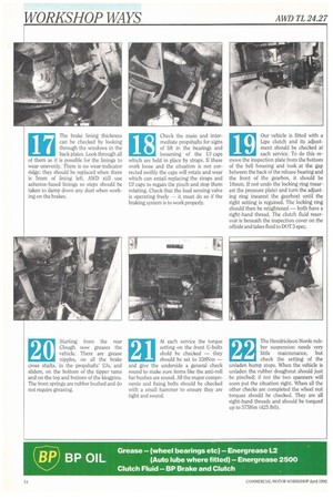
Having tilted the cab the fuel titter can be changed — this should be done at every service. The filter is on the nearside of the engine but is hidden behind the power steering reservoir making its removal difficult. Use a strap wrench for this, pull off the 0-ring over the central threaded section of the housing and replace it with the new one in the filter kit. Clough advises fitters to fill the filter with diesel before fitting it to the engine so there will be no need to bleed the fuel system. There is also a sedimentor in the fuel system and this should be cleaned out at each service. To do this remove the nut from the central bolt that secures the glass bowl. Clean out the bowl thoroughly and make sure the 0-ring is still properly seated in the housing. It is not necessary to fill the bowl with diesel before refitting it to the vehicle but do not over tighten the centre bolt as it will crack the glass bowl. The specified torque is 2Nm. With a tipper it is especially important to make sure the air filter is kept clean. In theory there is no need to disturb the filter unless the restriction indicator shows red, meaning the element needs changing. But on tippers Clough always removes the filter and cleans the housing out. The fan belt should also be checked for tension and signs of fatigue. There is an automatic tensioner so if the tension is lost there is a problem — either the belt has stretched too far or the tensioner has seized.
On Cummins engines it is important to check the level of inhibitor and antifreeze in the coolant system at each service. A 25% concentration of ethylene glycol antifreeze should be maintained all year round. Every two years the system should he drained, flushed and refilled with 30.5 litres of coolant. To check the inhibitor level take a sample from the header tank and analyse it using the kit available from Cummins agents. 10 If more inhibitor is needed it is added by changing the coolant filter. Again this is a
disposable canister-type filter which is set on the offside of the engine. Before removing the filter the tap should be turned off as shown. The filter is removed with a strap wrench and a little grease smeared on the new filter's seal before fitting. If extra inhibitor is needed it can be added to the header tank, but be careful to avoid running with too much inhibitor.
On the B service the valve clearances should be checked. This needs to be done when the engine is cold; the settings are printed on a plate attached to the engine. In this case they are 0.3rnm (0.012in) for the inlet and 0.6mm (0.024in) for the exhaust. There is a single rocker cover on this engine but its rubber seal does not need replacing unless it is damaged. Clough checks round the top of the engine to see that all is well.
11
12 There is a desiccant type
dryer in the air system. The canister containing the des iccant should be changed every year or on the B service. As the canister is pressurised it is important to drain all the air from the system before it is loosened. The element is removed by a strap wrench and the replacement is fitted hand tight after greasing the seal. On other services the 'wet' tank should be drained to ensure that the dryer is working properly. While in the area Clough checks the batteries as they are not sealed-for-life units. Having lowered the cab the fluid level in the tilt pump should be checked; it takes Dexron II.
13 On the B service the end
float in the front wheel bear ings should be checked. To do this jack up the front axle and release the park brake. Next remove the small hub cap, wipe the grease off and place the plunger of a dial test indicator (DTI) on the end of the stub axle. The magnetic base of the DTI should be fixed on to the wheel itself. By pulling and pushing the wheel the end float can be measured — it should he between 0.1mm and 0.3mm. If not remove the split pin and turn the nut until the correct setting is achieved.
Having checked the wheel bearings the king pins should be checked for lift. This is done in the normal way with a bar placed underneath the tyre and levered upwards. Any play must be in the king pins as the wheel bearings have been set. 14 15 Moving back beneath the
vehicle a colleague turns the
steering from lock to lock as Clough looks for fouling. That done the axle is lowered back onto the ground and the steering rocked lo detect signs of play in the ball joints. These are sealed-for-life units and musl be replaced if the wear becomes too great. A bar between the road spring ends and the brackets will show if there is excessive play in the bushes. The rear suspension is rubber so it does not need to be checked in the same way. 16 While there is still someone in the cab check the brake
actuation. Self-adjusting
Girling Z-cam brakes are fitted. If there is any problem with the system it will be revealed by a longer-than-normal stroke as the brake is applied. Listen for air leaks on the system as the brakes are applied and let off again and don't forget the hand brake. Use a bar to check for wear in the brake actuator arm bushes. 17 The brake lining thickness
can be checked by looking through the windows in the back plates. Look through all of them as it is possible for the linings to wear unevenly. There is no wear-indicator ridge; they should be replaced when there is 5mrn of lining left. AWD still use asbestos-based linings so steps should be taken to damp down any dust when working on the brakes.
18 Check the main and intermediate propshafts for signs
of lift in the bearings and loosening of the UJ caps which are held in place by straps. If these work loose and the situation is not corrected swiftly the caps will rotate and wear which can entail replacing the straps and UJ caps to regain the pinch and stop them rotating. Check that the load sensing valve is operating freely — it must do so if the braking system is to work properly.
19 Our vehicle is fitted with a
Lipe clutch and its adjust ment should be checked at each service. To do this remove the inspection plate from the bottom of the bell housing and look at the gap between the back of the release bearing and the front of the gearbox, it should be 18mm. If not undo the locking ring (nearest the pressure plate) and turn the adjusting ring (nearest the gearbox) until the right setting is regained. The locking ring should then be retightened — both have a right-hand thread. The clutch fluid reservoir is beneath the inspection cover on the offside and takes fluid to DOT 3 spec.
20 Starling from the rear Clough now greases the
vehicle. There are grease nipples, on all the brake cross shafts, in the propshafts' Ws, and sliders, on the bottom of the tipper rams and on the top and bottom of the kingpins. The front springs are rubber bushed and do not require greasing.
At each service the torque setting on the front U-bolts shold be checked — they should he set to 338Nm — and give the underside a general check round to make sure items like the anti-roll bar bushes are sound. All the major components and fixing bolts should be checked with a small hammer to ensure they are tight and sound.
21
22 The Hendrickson Norde rubber suspension needs very
little maintenance, but check the setting of the unladen bump stops. When the vehicle is unladen the rubber doughnut should just be pinched; if not the Iwo spanners will soon put the situation right. When all the other checks are completed the wheel nut torques should be checked. They are all right-hand threads and should be torqued up to 575Nm (425 lbft).