


Simple Design of Self-sprung Frame
Page 36
If you've noticed an error in this article please click here to report it so we can fix it.
A Resume of Patent Specifications That Have Recently Been Published. Copies May be Obtained from the Patent Office, Price 11each
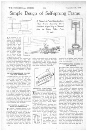
A N example of :or sion-bar springing reduced to its simplest form is shown in patent No, 562,982, by J. Coldwell and E. Boydell and Co., Ltd., Elsinore Road, Manchester, 16. The scheme is shown applied to the type of vehicle known as a ,dumper. A plan view is shown in the drawing, the vehicle
being carried on a built
ap frame comprising rear channels (1) and similar front members (2). The two sets of side members are united to a cross-tube (3) by welding, and it is: the resistance of this tube to twisting that gives the resilient action to the system. The shock of re-setting the bucket, which is considerable, is stated to be efficiently absorbed by this torsion tube.
IMPROVED DESIGN OF TUYERE FOR GAS PRODUCERS IMPROVEMENTS in the design of 1 water-cooled tuyeres for gas proJucers form the subject of. patent No. 563,012, from C. Cooper and Enness Sentinel, Ltd., Enness Works, Burlington Road, New Malden. The main object is to prevent heat distortion, which may lead to a short-circuit in the water path.
The drawing shows an " exploded " view to make the construction clear. The air tube I is surrounded by a conical jacket through which the water. is circulated, entering he the hole 2 and leaving via pipe 3: The 'essence of the patent is that the fins (9) are welded to both the air. tube and the outer jacket; this prevents them from buckling under heat and so permitting water to escape past the edges.
CONVERTING A LORRY TO A ROAD-REPAIRING UNIT
V) enable a standard vehicle to be used as the motive unit of'a road repairing machine is the object of a scheme shown in patent 'No. 562,973, by C. Cuppleditch and Aveling-Barford, Ltd., Invicta Works, Grantham, Lincs. The device is shown in the drawing with .a standard lorry in position upon it. A robtist frame is fitted with wheels which are driven from special rollers shaped to receive the tyres of the lorry. Reduction gearing may be used to
enable the device to travel at the excep. tionally low speed required for some road operations. The scheme may be applied to any variety of road-working machines, rolling and gritting operations being specifically mentioned.
IMPROVED CUP-WASHER FOR HYDRAULIC, BRAKES
THE cup-washer pf a master cylinder often has to uncover a filling port, and thus wear at this point may be much greater than on the rest of the circumference. To prevent this is the object of an improved, design shown in patent No. 562,872, by Bendix Aviation Corporation, South Bend, Indiana, U.S.A.
The drawing shows a pictorial view of the proposed cup-washer which is open at end I and closed at the opposite end where it abuts on the piston. The washer is provided with a number of helical grooves (2) which form the fluid • path on the back 75"/52.8.7.2 stroke, A ring of holes in the piston corresponds with the helical grooves, and the multiple jets of fluid issuing therefrom exert a turning
moment on the washer every time the brake is used, the washer, of course, being free to revolve. .
TWO LUBRICATING SYSTEMS IN ONE ENGINE • INTERESTING views on engine lubri1 cation are given in patent No. 562,487 by Century Motors Corporation, Dearborn, Michigan, U.S.A. It states that most of the wear on the crankshaft and its bearings is due to small gritty particles in the oil, which originate from the combustion chamber. It is claimed that if the oil . be maintained in a pure state, bearing wear is materially reduced. The patentee proceeds to describe an engine having a lubricating system for the cylinders and valves and a separate one for the crankshaft.
The amount of lubricant actually consumed by the " mains " and bigends is actually very small, and it is proposed to use a thin grease for this purpose'. The grease is supplied through a drilled crankshaft and reaches the main bearings, the throws and the gudgeon-pin. There is no attempt at a circulatory system, new grease being continually supplied under pressure. Every bearing is, however; fitted with sealing rings, but if leakage does occur the lubricant is added to only the general oil system of the crankcase. The grease can be injected by a small plunger worked by a pedal under the control of the driver., The engine is interesting in other ways; the drawing ,shows that unsplit big-ends are used, with needle-rollers running on hardened surfaces, a method also employed in the small-end. Unsplit bearings. necessitate a built-up crankshaft, and this feature is covered by an earlier patent which was reviewed in our issue dated July 21 of this year.