


A Gas Turbine for Road Vehicles
Page 54
If you've noticed an error in this article please click here to report it so we can fix it.
A Regard of Recently Published Patent Specifications
'THE success of the gas turbine in air1 craft is already encouraging inventors to investigate the possibility of employing this type of power unit for road vehicles, and patent No. 602,706 deals with some aspects of rotor design. The scheme goes even farther; it includes an automatic variable gear which adjusts the developed torque to the imposed load. The patentee is A. Gilbert, 132, Glencoe Road, Chatham, Kent. • The drawing shows the bladed rotors of the turbine; two are used, one being a first-stage rotor (1) which drives only the blower, whilst the other (2) forms the power output member. The blades (3) of the former have a fixed angle, but the output blades are variable over a considerable angle. The output shaft is not coupled directly to the blade wheel, but has a spring drive (4) interposed, so that a small angular difference is set up between the discs (5 and 6) in proportion tb the-applied torque. Each of the blades (7) is attached to a bevel pinion (8) and these can be rotated by the angular differential movement, so varying the blade angle. At rest, the blades would beset in the " top-gear " position, but when the gas begins to flow, the angle would be reduced until the ratio became low enough to deal with the load.
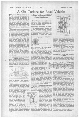
AN AGRICULTURAL TRACTOR FROM FRANCE
THE standard type of agricultural tractor has been known to turn over backwards with excessive drawbar pull, and to avoid the risk of this is the primary object of a design shown in
patent No. 602.599. The patentee is Bernard Moteurs, Rueil Malmaison, France.
The drawing shows an outline of the driving mechanism, all other details being omitted. The machine is trackdriven, the large front wheels being powered, whilst smaller ones at the rear act only as pulleys. The engine (I) is of the vertical single-cylindered type, and is built as a unit with the clutch and gearbox. The latter is provided with a projecting shaft (2) to act as a power take-off. The output shaft (3) of the gearbox runs forward, under the engine, and terminates in a worm which drives a worm-wheel (4) mounted on . a cross-shaft. Spur pinions on the end of the cross-shaft drive gears (5) fitted to each wheel. The cross-shaft is divided by a pair of clutch-cum-brakes for the purpose of steering the vehicle.
436 The tendency to turn over backwards under heavy load is reduced due to the bulk of the weight being located well forward of the rear wheels.
IMPROVED FLOATING REAMER
'THE floating reamer is probably the I. only workshop tool that will produce a given size of hole with complete certainty, and patent No. 602,860 shows an adjustable tool of this type. The patentees are J. Archer, and English
Steel Corporation, Ltd., Vickers Works, Brightside Lane, Sheffield, 9. .
The drawing shows a taper-shanked tool with the cutter-head in section. Two cutters (I and 2), or a single one and a dummy, are mounted slidably in a square hole. They are connected by a double-ended screw which, when turned, varies the overall reach of the two cutters, and therefore the size of the hole produced. To turn the double screw, a central head (3) is formed as a worm wheel and meshes with a worm (4) which can be turned from the outside.
The double-ended screw is not, as might be expected, a right-and-left-handed affair, but is right-handed on both ends, but of a slightly differing pitch. By this means, an extremely fine adjustment can be given by the worm, one turn of which gives only 0.005 in. on the hole diameter. If a quick, coarser adjust„ ment be needed, the cutters can be slid out and individually rotated, giving a variation of 0.050 in. per turn. The worm is fitted with a quick-release device to enable this to be done.
IP .11111k, ssisvssdess zuffisi
Ito
A SAFETY TYRE FROM HOLLAND A N inner tube containing two extra LA safeguards against sudden deflation,' is shown in patent No. 602,502, by A. Seeuwen, Nimeguen, Holland. In the drawing, 1 is the normal inner tube, inside which • there is a second one (2), The latter is further filled with a number of separate rubber chambers (3); these are in the shape of balls when deflated, but v7 hen under pressure become flattened into almost a continuous circle. The two tubes and the balls are all united into a single member by an adhesive introduced during assembly. A further feature of the patent is that the
innermost tube may be reinforced with canvas so as to create a non-extensible chamber. No details are given of the means for inflating the interior members, although the main tube is inflated in the usual manner through a conventional tyre-valve.
In practice, it is claimed that only one or, at the most, two of the chambers would become punctured, so that the effect on the tyre, as a whole, should prove negligible, HYDRAULIC PUMP OR MOTOR AT WILL
L-1 A DEVICE that will function as a pump if powered, or as an hydraulic motor if supplied with fluid under
pressure, is shown in patent No. 602,465, by the Coventry Gauge and Tool Co., Ltd., Coventry, and others. The working principle employed is that of axially sliding vanes which define a chamber of variable volume.
The action is best explained by a development drawing. A rotor is shown at 1, and its enclosing casing at 2. Six sliding vanes (3) are used, the end one being shown twice. The cycle of operations, when the device is used for a motor, is as follows: Considering a single vane (4), it is subjected to fluid pressure from an inlet port (5) and is thereby moved to the right, exhausting the fluid ahead of it from an exit port (6). It then encounters the sloping portion (7) of the track and rises until a slot (8) aligns itself with, and passes over, a chamber-dividing wall (9). As soon as the vane has passed this obstruction it moves to position 10, and is once again subjected to pressure from the next inlet port (11).
By this .means each working vane continually approaches the end of a closed chamber, and when the end is reached it "steps aside" to by-pass the wail, and then returns to the operative position. It is claimed that the design ensures complete freedom from pulsation.