


Patents Completed.
Page 22
If you've noticed an error in this article please click here to report it so we can fix it.
Albion Paraffin Carburetter. Wolseley Two-part Chassis. Speedometer Driving Gear. Schneider Coupling.
ALBION MOTOR CAR CO., LTD., and T. B. MURRAY, No. 20,980, dated 17th September, 1913.—In this carburetter the air and the fuel are both measured in their required proportions before any mixture is made. The air-inlet is on the
right-hand side adjacent to the float-chamber, and the suction of the air through the inlet passage draws a proportional amount of fuel up from the jet nozzle into a channel in the bottom of the inlet passage. The fuel flows thence down into a small sump in the bottom of the mixing chamber. Air is drawn in through this inlet passage by a pump situated above the mixing chamber, and is delivered from the pump through a non-return valve to a jet-nozzle which projects into the sump below the normal level of the liquid. The liquid is sprayed and the mixture passes away to the left through a superheater. This superheater is provided with a series of heavy gills and also with a series of thin tubes through which the exhaust is circulated.
SOCIETE TH. SCHNEIDER ET CIE., No. 9845, dated under the International Convention, 30th June, 1913.—The object of this invention is to provide a construction of rear axle and cardan-shaft transmission in which the various thrusts and reactions from the driving-wheels can be trammitted to the chassis without interfering with the action of the main roadsprings.
The cardan-shaft tube is fixed rigidly to the rear bridge, and is provided at its forward end with two inwardly directed shoulders receiving a ball bearing between them.
The cardan shaft itself is provided with two outwardly directed shoulders which also receive the ball bearing between them. The thrust of the driving-wheels is transmitted through the rear bridge and the tube, and is received by the ball bearing; the thrust of the cardan shaft is transmitted through the universal joint to the driving shaft in the gearcase and thence to the chassis This construction amounts to jointing the rear bridge to the chassis at a single fixed joint in the centre of the cardan joint.
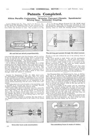
E. C. R. Maims (MOTOR PATENTS CO.), No. 25,136, dated 4th November, 1913.—The driving gear described in this specification for speedometers is arranged for connection to a steering wheel in which the steering knuckle is mounted
directly on the axle without the use of the ordinary form of swivel-pin.
The wheel spindle is made hallow and the speedometer driving-shaft passes through it. On the inner end a skewgear is mounted in a pocket and meshes with a second skew. gear on a driven shaft, which in turn is connected to the flexible transmission shaft. The gears are totally enclosed in a pocket which constitutes an oil bath.
The spiral gears are preferably arranged with their point of contact in line with the axis of the knuckle, so that both the driving and driven gear can be removed as units together with the parts attached to them. Various methods of construction are described and illustrated in the specification.
THE WOLSELEY TOOL AND MOTOR CAR CO.., LTD., A. McCollMACK and A. A. REMINGTON, No. 18,685, dated 18th August, 1913.—The main feature of this invention consists in constructing the principal portions of the mechanism out of a front and back unit. The ordinary frame is dispensed with and its place is taken by two straight side-members which are preferably of timber ; these are inclined towards one another at the front so as to provide the required width at the rear and allso to allow for ample steering lock.
The front unit consists of the engine and its controlling mechanism, cantilever springs and the front axle and road wheels. The springs are mounted on brackets on the engine. frame and the latter is secured to the wood stretchers by suitable brackets fixed on each end of the engine-frame. This latter is held in place by eight bolts, and when these are removed the whole ]front unit can be detached.
The rear-unit similarly has the springs fixed on brackets connected by a tubular cross-member. When the brackets are detached from the wood stretchers, the whole of the rear unit, driving gear and road wheels, can be removed.