


ELECTRIC-VEHICLE COMMITTEE'S STANDARD CHARGING PLUG.
Page 14
If you've noticed an error in this article please click here to report it so we can fix it.
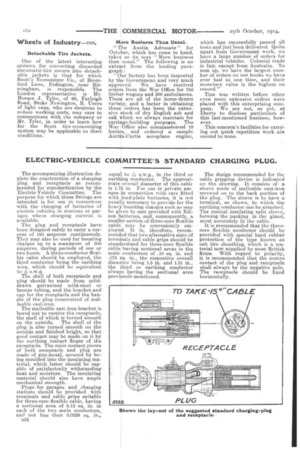
The accompanying illustration depicts the construction of a charging plug and receptacle as recommended for standardization by the Electric-Vehicle Committee. The purpose for which these fittings are intended is for use in connection `with the charging of batteries of electric vehicles in stations or garages where charging current is available.
The plug and receptacle have been designed safely to carry a current of 150 amperes continuously. They may also be used for boosting charges up to a maximum of 300 amperes, during periods of one or two hours. A three-conductor flexible cable should be employed, the third conductor being the earthing wire, which should be equivalent to s.w.g.
The shell of both receptacle and plug should be made from soliddrawn galvanized mild-steel or bronze tubing, and the bracket and cap for the receptacle and the handle of the plug constructed of malleable cast-iron.
The malleable cast-iron bracket is bored out to receive the receptacle, the shell of which is turned smooth on the outside. The shell of the plug is also turned smooth on the outside and finished bright, so that good contact may be made on it by the earthing contact finger of the receptacle. The main contact pieces of both receptacle and plug are made of gun-metal, secured by being moulded into the insulating material, which latter should be capable of satisfactorily withstanding heat and moisture. The insulating material should also have ample mechanical strength.
Plugs for garages and charging stations should be provided with terminals and cable grips suitable for three-core flexible cable, having a sectional area of 0.15 sq. in, in each of the two main conductors, anti not less than 0.0229 sq. in., .B2S
equal to s.w.g., in the third or
earthing conductor. The approximate overall diameter of this cable is 1.75 in. For use in private garages in connection with cars fitted with lead-plate batteries, it is not usually necessary to provide for the heavy boosting charges such as may be given to cars provided with Edison batteries, and, consequently, a smaller section of three-core flexible cable may be conveniently employed. It is, therefore, recommended that two alternative sizes of terminals and cable grips should be standardized for three-core flexible cable having sectional areas in the main conductors of .10 sq. in. and .075 sq, in., the respective overall diameter being 1.5 in. and 1.31 in., the third or earthing conductor always having the sectional area previously mentioned.
The design recommended for the cable gripping device is indicated on the drawing. It consists of a sleeve made of malleable cast-iron screwed on to the back portion of the plug. The sleeve is to have a terminal, as shown, to which the earthing conductor can be attached. The conical insulating split sleeve, forming the packing in the gland, must accurately fit the cable.
It is recommended that the threecore flexible conductor should be provided with special bard rubber protection of the type known as cab tire sheathing, which is a material now supplied by most British firms. With regard to polarity, it is recommended that the contra contact of the plug and receptacle shall always be the negative pole. The receptacle should be fixed horizontally.