


Patents Completed.
Page 20
If you've noticed an error in this article please click here to report it so we can fix it.
BEARINGS.—Mair and Another.—No. 3,747, dated 31st December, 1907.—This invention relates to anti-friction bearings in which rollers are arranged to take radial strains, and balls to take the end
thrusts. The inner bearing member (2) has a circumferential groove (3) which ac.commodatea a aeries of rollers (4) separated by balls )51. The outer bearing member is made up of two parts .(6, 71, which also form a recess (8) for the reception of the rollers (41. The sides (9) cf the recesses (8, 3) are curved so as to form races for the balls (5). It will be seen that the radial strain of the bearing will be taken by the rollers (4) running in the recesses (3 and 8), and also the side thrusts will be taken by -the balls (5).
DISTRIBUTOR.—The Electric Ignition Company.—No. 1,984, dated 29th January, 1908.—This invention relates to
an improved casing for a distributor which permits of the various parts of the distributor being examined while working. The casing comprises a cylindrical body part (a) which may be made of glass or celluloid, and end plates (d and b) ; 1ndia-rubber rings (j and c) are interposed between the glass casing (a) and the plates b, d). The feeder and distributing ter minals (e, ell are carried by the plate (d) . The plates (b and d) are held together by means of bolts (g) provided at one end with an ordinary nut, and with a butterfly nut (k) at the other end. The glass is not subjected to pressure by the bolts.
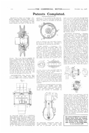
TUBE JOINTS. — Crompton. — No. 27,070, dated 7th December, 1907.—The -tubes (B and B1) to be joined, are expanded or bell-mouthed at their ends, so as to accommodate an externally-coned tube (C). Prior to expanding the ends of the tubes (B and B1), externally-screwed rings (A) are slipped over them. One of the rings (A) has a coarser thread than the other, and both are screwed into a
nut (D), which is also provided with two screw threads, one of which being of coarser pitch than the other. To make the joint the two coned ends of the tubes are brought up against the internal cone piece, the coupler is brought over the joint and the fine-threaded abutment screw is screwed into the coupler as far as it will go, then the other male screw is tightened up to bling the joints together.
INTERNAL-COMBUSTION ENGINE. —Dunsmore.—No. 25,960, dated 23rd November, 1907.—This invention relates to an internal-combustion engine in which the cylinder is scavenged by air previously compressed within the crank chamber. The crank chamber (A) is provided with an auto matic non-return valve (B), through whicl air is drawn at each upward stroke of th piston, or the air may be drawn throng] ports (C) which are uncovered by th piston as it re.aches the top of its stroke It is then compressed by the downwar( stroke of the piston, and is finally ad mitted to the cylinder through ports (D which are uncovered by the piston. I will also be seen that the cylinder will la surcharged with air an the completion the suction stroke.
MAGNETO IGNITION. — Chamber Motors, Limited.—No. 7,747, dated 7t1 April, I908.—This invention relates to th driving connection between an internal combustion engine and its magnet igniter, wherein a spring arranged betwee: the driving member of the motor and th armature shaft is put under tension dux ing the period that the latter is held sta tionary, and. is then released so as t rotate the armature, and thereby to caus a spark sufficient for ignition. A ratche (a) having a number of slots (b), corn sponding to the number of firing point per revolution, is secured to a stationar part of the magneto frame (c). A sleev (d) is mounted upon the armature shaft (e and it carries a pawl (f), adapted to er gage in one or other of the slots (b) unde the action of a spring (g), when the shai (e) is being slowly rotated. The drivin shaft (h) is provided with two arms (1) t which springs (k) are attached, the latte being also secured to the sleeve (d) b means of hooks (1). When the engine c driving shaft (h) is stationary, and als under normal running conditions, tk arms (i) are in contact with stops (m) upo the sleeve (d), but when the shaft .(h) slowly rotated, as for instance when th engine is being started by hand, the ern (i) move away from the stops (m) and -Lei sion the springs (k) until one of the ern V) strikes a balance weight (n) connecte with the pawl (f), and disengages a latter from its respective slot (b) in tt ratchet (a). The ratchet is thereupon e leased and, together with the armatur, rapidly rotates under the action of ti springs (k), thereby generating sufficiet current for ignition.